ARLISS 2004 (3UP)
Some members of AERO-PAC,
organized by Tom Rouse, worked with Professor Bob Twiggs
of Stanford to build rockets to launch student satellites from amateur rockets at the
Black Rock Desert.
For more information about the program, see the
ARLISS web site.

The first ARLISS launch was held on September 11, 1999 after much planning. Two teams from Japan, a team from Arizona and a team from Redwood City, CA each built three "can sats" and the ARLISS team provided four rockets to launch them. I helped out here and there with construction, but mostly I took pictures.
I participated as a flier in the second (2000), third (2001) and fourth (2002) years, with my first ARLISS rocket, the ARLISS 2000 (Coker's Cans).
In 2002, the rocket was damaged on recovery of the second flight. It could probably have been fixed, but I decided to rebuild it since I also wanted to make some changes to the design to make it easier to prep. The page describes my new ARLISS rocket for the 2004 seasons, called the ARLISS 2004 or 3UP.
The Pictures
 |
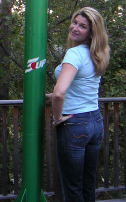 |
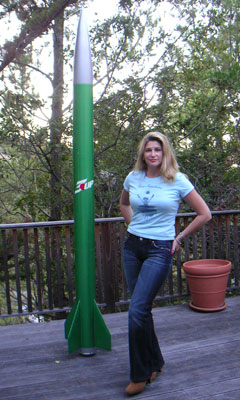
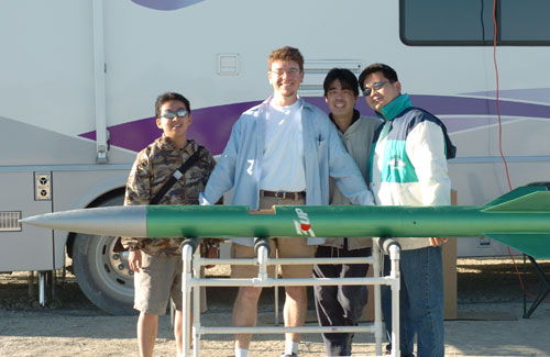
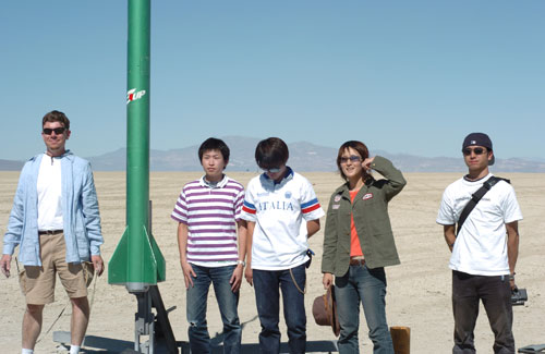
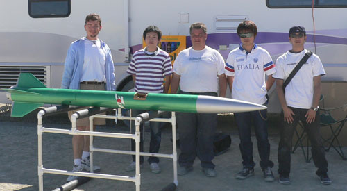
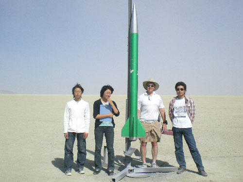
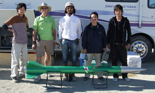
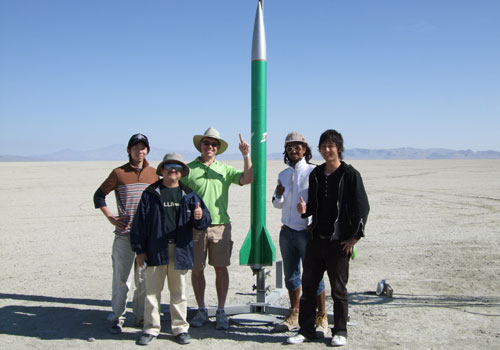
The rocket was completed in early September, just in time for XPRS at the end of the month! Here my lovely wife plays spokesmodel for the latest rocket in my fleet.
XPRS 2004 was a fantastic launch with three days of perfect launch weather with moderate temperatures, clear skys and no wind. We launched ARLISS rockets on Friday and Saturday. Due to having forgotten a few things, both of my flights were on Saturday.
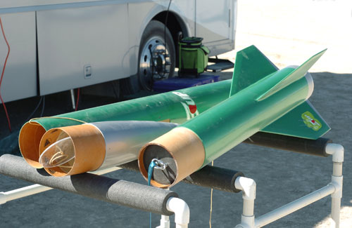
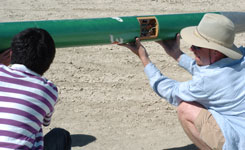
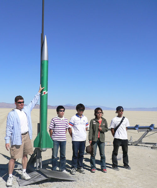
We arrived on Thursday for setup and in the picture above you can see my new ARLISS rocket unpacked and ready to carry a payload. (The 3-can logo on the fins was a last-minute addition which didn't survive the first flight.)
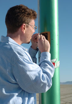
I was originaly scheduled for the first first flight Friday morning (at 8:00am), but I didn't realize that my new no longer had a serial port so it took me a while to get the G-Wiz configured. By the time I was ready in the late morning, I was bumped to first flight of Saturday morning.
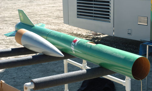
Above is the rocket prepped and ready on Friday afternoon. The nose is off ready for the carrier and payload and the electronics bay hatch is off ready for arming the electronics. This new design really did turn out to be much easier to prep.
Flight 1: T.I.T. Open Class
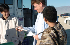
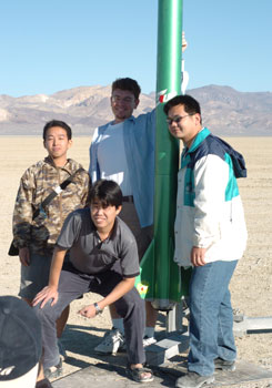
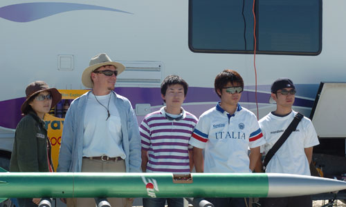
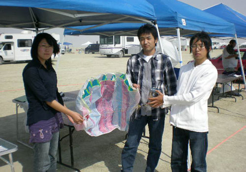
My first flight was Saturday morning. The payload was an open-class wheeled vehicle in the "come-back competition" by a team from the Tokyo Institute of Technology. They even gave me a beautiful Japanese fan.
 |
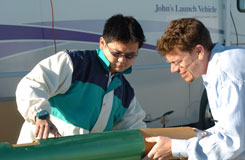 |
The rocket was ready to go when they arrived and all we needed to do was integrate their payload. All that meant was tying the line to the bottom of the carrier and installing the carrier and nose.
Then it was out to the range for the launch. Luckily, there isn't much of a line at 9:00am!
We got right out to the pad and set up the rocket. Everything worked out just as nicely as I had hoped, proving again that this new design was working out.
 |
 |
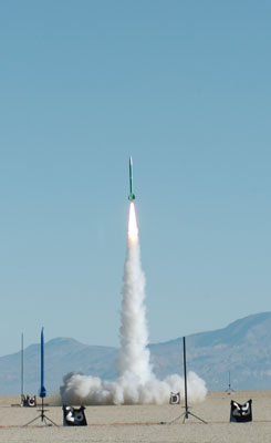
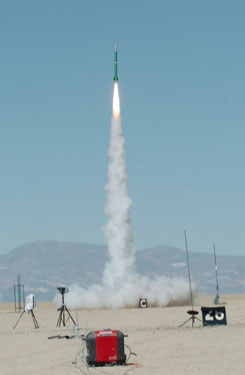
Back to the flight line and a few minutes later we were off!
 |
 |
I tried using my Adept tracker, but wasn't able to get any signal from it on my Icom ham hand-held radio. So, we ended up driving way out, much farther than the rocket landed in the vew low wind.
 |
 |
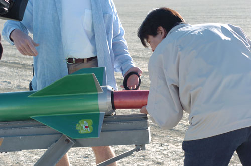
We found the booster first, then the payload section. Unfortunately, the charge wasn't strong enough to eject the carrier and we found the payload still in the carrier and the carrier still mostly in the rocket. This counts as a failure since the payload wasn't properly deployed, but at least the payload wasn't damaged and the team was able to fly it again. For the next flight, I used a 2g charge instead of the 1g charge used the first time.
| Max Altitude: | 12,253 f | |
| Max Acceleration: | 286.4 f/s/s, 8.9 G | |
| Max Airspeed: | 1095 f/s | |
| Time to Apogee: | 28.06 s | |
| Time to Burnout: | 5.38 s | |
| Altitude at Burnout: | 3528 f |
This new airframe was significantly lighter than the traditional ARLISS rockets. The fiberglass airframes and aluminum fin cans bring the rocket up to about 45lbs lift-off weight, while mine was only 38lbs on the pad. This is the major reason for the higher altitude. (My first ARLISS rocket lifted off at 44# and flew to an average of 11,700 feet; a 14% lighter rocket flew 4% higher.)
Flight 2: Tohoku Open Class
My second flight was Saturday afternoon. The payload was another open-class experiment (not part of the come-back competition) by a team from Tohoku University.
I was able to prep the rocket quickly the second time and was ready to fly again by noon. The students arrived and we quickly installed their payload and buttoned up the nose of the rocket.
 |
 |
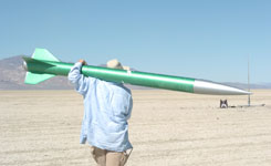
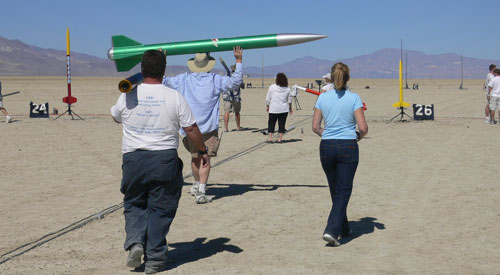
On Saturday afternoon, the RSO line was a bit longer, but we still made it out to the pad with little delay. As you can see, having a light rocket makes it easy to carry. (The motor was not installed until the rocket was loaded onto the rail.)
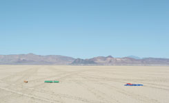
At the 500 foot pads, at the same time, was Ed Hackett's ARLISS bird with another student payload and Peter Clay's 2-stage rocket. After joking about it, we decided just to drag race all three rockets at the 500-foot pads.
 |
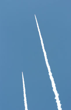 |
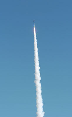
I didn't get a good picture of all three rockets taking off, but it looks like my rocket won the drag race! You can still see Peter's rocket on the pad (to the right of mine) in the left photo and it seems that my rocket is beating Ed's in the right photo!
 |
 |
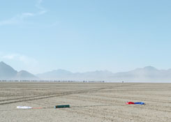
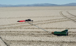
We found the three pieces strung out in a line to the northeast of the launch site. (You can see the Black Rock prominently at the center of the right photo.) The rocket performed perfectly this time and was again recovered without damage.
| Max Altitude: | 12,223 f | |
| Max Acceleration: | 323.2 f/s/s, 10.1 G | |
| Max Airspeed: | 1064 f/s | |
| Time to Apogee: | 21.31 s | |
| Time to Burnout: | 4.69 s | |
| Altitude at Burnout: | 3046 f |
The second flight looks a lot different from the first, but that may be because there were some problems reading the data from the G-Wiz MC and we had to do an "emergency read," which may case data to be read incorrectly.
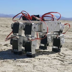
Below are pictures of the Tohoku payload, sent to me by Akiko Miwa. They show the walking robot which is very cool. According to her:
"The payload is a legged type robot which can walk on hard soil little by little. However, on the mission its legs sank because the landing point had very soft soil and it so was not able to walk."
 |
 |
|
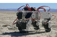 |
On the left is the robot on the playa. Top right is the robot just landed and bottom right shows it walking along the playa. (Photos by the Tohoku team.) This is a great looking robot!
Below are more pictures they took as we were getting ready to launch.
 |
| The rocket is loaded and ready. |
 |
| (It's nice to have a light rocket.) |
 |
| We're ready to go. |
I want to thank the Tohoku team for sending me these pictures and letting me know more about their payload. Thanks!
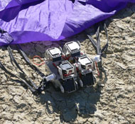
Flight 3: Akita University Parafoil
My first flight at ARLISS/XPRS 2007 was an Akita University (Japan) open class come-back project based on a streering parafoil. The ARLISS launch turned out to be almost entirely blown out due to high winds. (We had winds gusting up into the 30mph range Wednesday through Friday.)
The pictures above and below, taken by the students, show their parafoil project.
We went out to the pad once, then had to scrub due to high wind. Later that afternoon, we were finally able to fly.
There were gusty winds, but the flight was normal. The G-Wiz LC beeped out 13,431' (4094m). The data from the G-Wiz MC:
| Maximum Altitude: | 12,436 f (3790 m) |
| Maximum Airspeed: | 1069 f/s (Mach 0.97) |
| Maximum Acceleration: | 283.74 f/s/s (8.8G) |
| Descent Rate: | 28 f/s |
| Time to Burnout: | 5.56 s |
| Time to Apogee: | 25.9 s |
| Flight Length: | 478 s |
Flight 4: Tohoku University Rover
My second flight at ARLISS/XPRS 2007 was a Tohoku University (Japan) open class come-back project based on a 2-wheeled rover. After days of delays, mostly due to the wind, we finally launched on Saturday morning.
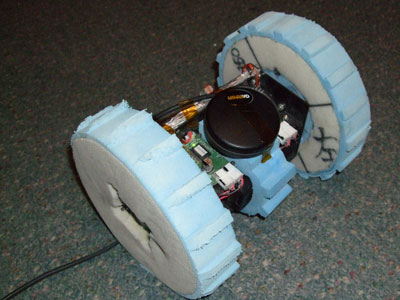
Above is a picture of the rover payload, taken by one of the University team members. They had the clever idea of using foam wheels that would compress inside the carrier yet be larger when deployed, which is better for handling ruts and bumps on the playa.
Finally, after many delays, the payload and rocket was loaded and ready to fly! The pictures above and below were taken by Tom Rouse and are here courtesy of the students. (None of my own pictures turned out as I had messed up my camera's settings!)
Launch conditions were perfect and the flight was normal. The G-Wiz LC beeped out 13,485' (4110m). The data from the G-Wiz MC:
| Maximum Altitude: | 12,418 f (3785 m) |
| Maximum Airspeed: | 1045 f/s (Mach 0.95) |
| Maximum Acceleration: | 279.67 f/s/s (8.7G) |
| Descent Rate: | 27 f/s |
| Time to Burnout: | 5.69 s |
| Time to Apogee: | 25.3 s |
| Flight Length: | 488 s |
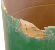
The forward end of my payload section was damaged on landing on this flight:
 |
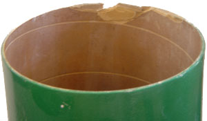 |
This sort of damage is a typical failure for phenolic, especially when impacting on hard surfaces. Luckily, it can be repaired fairly easily.
The Design
Rebuilding a rocket is a good time to make those design changes that you thought of after having flown the rocket a few times. The ARLISS 2000 (Coker's Cans) rocket was build using the standard ARLISS pattern with as many removable parts as possible and using Hawk Mountain fiberglass tubing.
I found that the design was hard to prep because there were just too many parts with all the separate bulkheads. My first design change was to integrate the two bulkheads around the electronics bay into the bay itself, making that just a single piece.
The second problem with the design was related to packing the parachute. In the old design, the recovery area was in the forward end of the aft airframe, but mostly inside the coupler bolted to the forward airframe. Also, the ejection charge had to be left loose and placed in the booster airframe before the laundry since most of the space was opposite the electronics bay. (Actually, even this wasn't perfect because the forward 'chute could get stuck inside the coupler.) Packing the recovery system and assembling the rocket was tricky because it was necessary juggle the laundry and ejection charge while coupling the rocket together.
The fix for this was to swap the tubes around and make the forward airframe 48" long and the aft airframe 32" long and switch to a more standard "backwards ejection" design. It also makes the recovery area a bit fatter and shorter (while increasing the volume by 12%). The parachutes are entirely in one section of airframe which makes packing much simpler. Also, the ejection charge moves to a location where neither parachute can remain stuck in the airframe. Not to mention that it is fixed to the electronics bay, which removes any loose wires and makes prep and assembly easier. (This will also allow use of the Rouse-Tech CO2 ejection system.)
Download the PDF drawings of the new overall airframe and the changes from 2000 to 2004.
Just as a matter of preference, I switched from fiberglass tubing to reinforced phenolic and from bolt-on aluminum fins to fixed built-up composite fins. I find the fiberglass tubing heavy and difficult to work with and the couplers don't fit the tubing well. The new airframe is Giant Leap flexible phenolic, laminated with fiberglass.
The aluminum fins tend to bend and I don't like the look of them as much. In 2003, Tom Rouse increased the size of the fins and had a new set of bolt-on aluminum fins made. My fins match the size of the new ones with a wider semi-span (6") and a longer root (16").
In the end, the airframe ended up weighing only 15lbs, despite no real attempt at weight reduction. Gotta love those composite materials!
| Section | Weight (lbs) |
|---|---|
| fin can (w/ tail cone and retainer) | 8.0 |
| payload (w/ electronics bay) | 5.2 |
| PML nose (w/ acrylic plate) | 1.9 |
| total airframe (w/o recovery) | 15.1 |
Below are subsections with more details on the different parts of the rocket:
See the ARLISS web site for more info.
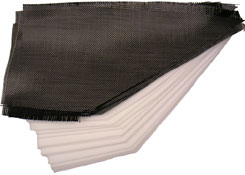
Composite Fins
My favorite technique for making fins is building them up using carbon fiber cloth and a core material (either closed-cell foam or balsa wood). This produces a very light and stiff fin and makes it easy to build any profile desired.
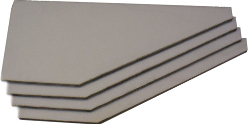
For the ARLISS rebuild, I decided to use 3mm Rohacell® 71 closed cell foam for the cores. This material comes in precisely formed sheets and is easy to work with. The closed cell foam is much nicer to work than Styrofoam® or green foam because it doesn't make the same horrible mess.
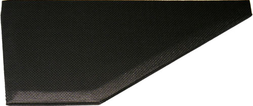
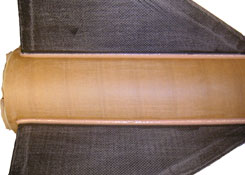
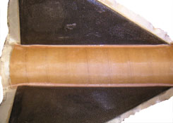
As you can see in the cross-section above, there are three layers of foam core and four layers of carbon fiber. This provides incredible stiffness with very little weight. The outer two layers of core are tapered at the edges to make a pleasing profile and the edges of the fins are finished with a piece of carbon fiber rod to form a durable edge.
The first step was to lay up the cores: the three pieces of foam and the two pieces of carbon fiber cloth between them. This created the main body of the fins, leaving the outer pieces of carbon fiber until after the fins were shaped.
|
To the right you can see the materials for the layup:
twelve pieces of foam and eight pieces of carbon fiber cloth.
|
 |
|
 |
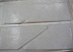 |
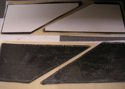
Note that the cores were cured in a veneer press to make them flat (above right). Once the cores were ready, the fin blanks were cut out. To make this easier and more consistent, the four cores were stacked together with double-stick tape and cut all at once on the band saw.
Above you can see the four cores cut out and ready for forming. The next thing was to taper the edges at a 10° angle. The taper was made so that the outer cores were tapered, with the taper ending at the carbon fiber layers. This left the center core intact and a third of the edge still flat.
 |
 |
To create a solid edge and provide a more pleasing finish, I then bonded 1/8" carbon rod along the edges. In the picture above left, you can see the rod taped and tacked with CyA in preparation for bonding with epoxy. Finally, the outer skin of carbon fiber cloth was applied to the fins and back the went into the vacuum bag. This time, the FoodSaver® is used since, without any base board, it will accomodate the tapered edges of the fins.
Above you can see a single completed fin. Gotta love the look of carbon fiber! Edging the fins with the rod also makes a strong and clean look.
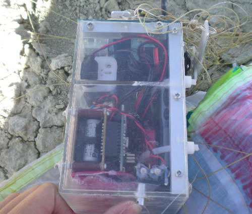
Electronics Bay
The electronics bay slides into the forward airframe and is 8" long overall. This includes space above and below for bridle attachment and two ½" bulkheads, which leaves just enough room (5¼") for two G-Wiz units. (The overall drawing has a diagram of the electronics bay.)
The first thing to do was build three bulkheads. Actually, one of them is for the coupler in the aft airframe, but they're similar so I built them all at the same time.
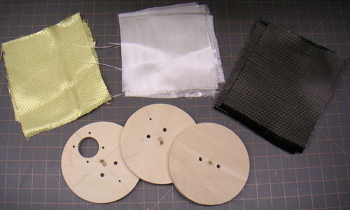
Here are the components for the three bulkheads. I used Kevlar® fabric and 6oz fiberglass on the hardware side (inner side of the elecronics bays and bottom side of the aft coupler) and carbon fiber cloth and fiberglass on the exposed side.
 |
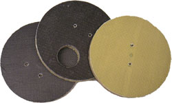 |
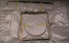
Above you can see the three bulkheads in their vacuum bags (using the trusty FoodSaver® again) and when finished and trimmed.
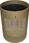
The next step was to cut a piece of coupler to 8" long and cut out the access areas in the front and back. The front opening (shown here) will be used to arm the electronics on the pad and a (corresponding hatch was cut into the forward airframe).
Finally, everything was assembled and the electronics bay is done. Note that a strip of coupler tube was bonded in on the outside of each end of the bay, locking the bulkheads into place. This helps to form a very strong unit as well as create a small well at each end of the bay.
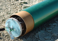
Booster Section
The booster section is a straight forward rear ejection design. The motor mount tube fills the booster; it's 36" long and easily able to accomodate a 4-grain AeroTech motor (such as the M1939). The forward end of the MMT goes up inside the coupler which is bonded to the aft airframe.
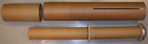
Above you can see the main parts of the booster laid out. At the top is the coupler and the tube, already slotted for the four fins. Below is the motor mount tube with the central centering ring mounted. The forward CR is actually inside the coupler (to give the coupler and forward end of the body tube more strength). The aft CR is temporarily placed on the tube, along with the tail cone.
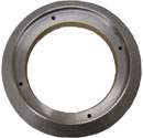
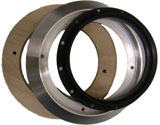
The aluminum tail cone you can see at the end of the MMT is a piece made by Tom Rouse. This very nice cone is recessed to accomodate an Aero-Pack retainer and makes a very clean way to finish the aft end. (I had to cut a rabbet around the aft outside edge of the CR to accomdate the lip since the tail cone was designed to be used with the standard ARLISS fin can insert.)
 |
 |
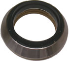 |
Above left, you can see the ring sitting on the aft centering ring. In the center, you can see the CR, Tom Rouse's tail ring and an Aero-Pack 98mm retainer. On the right, you can see the three parts together as they will be bolted onto the rocket. The aft CR is bonded into the airframe and the tail cone and retainer are bolted to it.
Instead of the usual technique of laminating the tube with fiberglass first, then slotting it and installing the fins, I decided to mount the fins first and laminate afterwards. The body tube was slotted for the fins, which ended up being just a hair over 3/8" thick (see above). I bonded the fins at the bottom to the motor mount tube using epoxy in the usual way.
 |
 |
In the pictures above, you can see the fin fillets on the left and then the tip-to-tip fiberglass reinforcement on the right. Note that this was applied to the bare tube, and the fiberglass continues up on the airframe to the forward edge, effectively laminating a quarter of the airframe at a time.
Once around (four applications) and both the airframe lamination and fin tip-to-tip reinforcement were complete.
Sustainer Section
The sustainer airframe is a single 48" piece of body tube. I made this section as long as possible to maximize the amount of space available for recovery. The booster and sustainer recover using separate parachutes, which means more space than usual is needed. Luckily, a 6" body tube provides a good amount of space and I have extra diameter and extra length over the standard ARLISS design.
The only real feature of the sustainer is the arrangements for the electronics bay. The bay is built into a coupler (see above) which slides into the sustainer airframe from the top. A section of coupler below reinforces the bay for the stresses of main recovery and aids in alignment during prep.
I also cut a hatch into the airframe to make it easy to arm the electronics on the pad. The bay is pretty full with two G-Wiz MCs and four batteries so I left out power switches. The electronics are armed by connecting the batteries so having a nice large hatch to reach into is necessary.
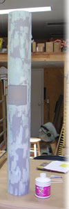
Here you can see the airframe section after it has been primed and the surfaced filled with spot filling compound. Not much to it!
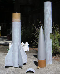
Painting
As always happens, the pace of construction increased as the deadline approached. In this case the deadline was the XPRS 2004 launch in late September so by the end of August, time was growing short.
The rocket, like my first ARLISS rocket, was to resemble a soda can, but this time 7UP® instead of CocaCola®. So the main color was metallic green with the nose and base of the fin can a "bare aluminum" color.
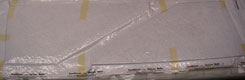
The actual painting didn't happen until August 28, and I wet sanded and painted the rocket in a maraton session. I started wet sanding at 9:00am and the last picture below was taken at 10:30pm.
 |
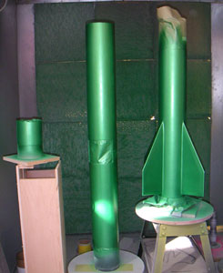 |
|||
| 2:00pm: wet sanding done, | 6:00pm: airframe painted green, | |||
 |
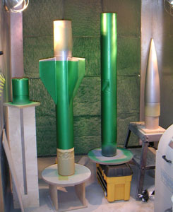 |
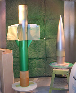
|||
| 9:00pm: nose and tail painted, | 10:30pm: clear applied. | |||
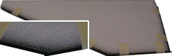
In the photos above, there are four separate parts (from left to right in last photo): the hatch cover, the aft section, the forward section and the nose. This was a reasonably simple paint job, with only one part that had two colors.
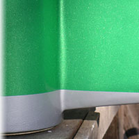
One thing I did improve on this time was the two colors in the aft section; I managed to get a razor sharp line between the green and silver! In the past, I would always get some bleeding under the tape, making a fuzzy edge.
After the green had set (2 hours), I masked off the area to be painted and sprayed green again to seal the tape. Then I painted the silver. This adds a step (mixing up another pot of the base color to seal the masked area), but results in a perfect line. After the masking was removed, there was a noticable raised edge, which I (very) lightly sanded with 600 grit paper. This left scratches in the silver in some places so next time I will use 1000 grit paper.
I'm very pleased with the results! Note that I use PPG products, specifically the DBU 2-stage coatings. With this system, you can apply color coats at frequent intervals and after you're finished with all the colors, you paint the clear coats. (I used 4 coats of each color and 4 of clear on this rocket.)