Nike-Tomahawk
In March 2007, several people asked me to give a seminar on composite construction techniques so I decided to oblige. Of course, that led to a trip through Rockets of the World looking for good model to build.
I was looking in the Nike booster section because the fin profile would provide a good reason to do built-up composite fins and found the Nike-Tomahawk. The Nike booster is a favorite rocket for modellers as is the Tomahawk sustainer. As it turns out, the Tomahawk also has fins with an interesting profile.
Note that I've modeled another Nike-boosted rocket, the Nike-Asp. That rocket used a mis-matched (not scale) booster, although I did make custom airframe tubing and built-up composite fins. This Nike-Tomahawk would expand on those techniques and be properly to scale.
The Pictures
The Design
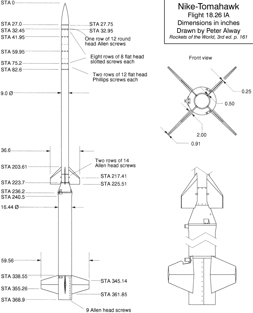
I decided to model the Nike-Tomahawk at 45% because that results in a sustainer based on a minimum diameter 3.9" aiframe (4.05" O.D.). (The Nike booster O.D. is 16.44" and the Tomahawk sustainer O.D. is 9.0".) That makes the model booster O.D. 7.4", which doesn't match any standard tube but is quite close to standard 7.5" coupler tubing (just under 7.5" O.D.). This makes an overall height for both stages of 166" (13'10" or 4.2m).
Of course, I used the scale drawing from Rockets of the World (Third Edition, page 161), as the basis for my model.
I decided to use the sustainer motor itself for the interstage coupler. This works well for minimum-diameter rockets, but requires that the motor be retained from the forward end. Also, the thrust of the motor must push on internal structure since the motor case thrust ring must be removed.
The target sustainer motor was the long-burning Cesaroni M520, but I also wanted to potentially accomodate the longest AeroTech case (used by the N2000). Leaving 4" of motor hanging out the aft end for coupling, the sustainer had to accomodate up to a 36" motor case. Given that I wanted to use standard "backwards ejection" dual-deployment, that set the parameters for the sustainer sections.
There is much more space to work with in the booster. And, since I was planning to use single-stage deployment, the motor could take up the majority of the space. The booster can easily accomodate a 6" motor 42" long.
See my overall drawing for scaled-down dimensions and layout of the internal structure.
This page, particularly this design section, is very long so I have added a table of contents to make navigating it easier.
- Nike Booster Fins – built-up composite fins
- Booster Airframe – reinforcing standard phenolic tubing
- Interstage Coupler – pocket for sustainer plus double-cone shape
- Booster Electronics Bay – a large-diameter squat space
- Tomahawk Sustainer Fins – more built-up composite fins
- Sustainer Airframe – using minimum-diameter carbon tubing
- Sustainer Ignition – sustainer ignition electronics bay
- Sustainer Electronics Bay – packing a lot into 3.9"
Nike Booster Fins
Built-up composite fins were the original reason for building this rocket, so of course they are a primary feature. This section describes the process of making the booster fins. A similar process was followed as with my Just Married and Nike-Asp rockets. Nike-style rockets are popular so these techniques should be useful to many modelers.
|
Step 1: Core Blanks
First 3mm Rohacell sheet was cut to the fin shape and 3mm carbon fiber kite spars we tacked to the leading and trailing edges with CyA. Step 2: Core Reinforcement Next carbon fiber was laminated to each side of the core, providing stiffness. Step 3: Balsa Profiles Then four shaped balsa profiles were epoxied to the cores to create the profile. Step 4: Surface Reinforcement Finally, carbon fiber was laminated to both sides of the profile completing the fins. |
 |
Step 1: Core Blanks
I like to use light materials for the cores of composite structures since the strength and stiffness comes from the reinforcement (carbon fiber in this case). There are two kinds of core material in these fins: Rohacell and balsa wood. In the case of the cores, I used 3mm Rohacell.

Rohacell is flat and comes in many thicknesses so it makes a good core for a flat part. (It doesn't bend well, but is very uniform.) It's also easy to work with since it doesn't produce the nasty particles that other foam products do and can be easily and accurately cut using a rolling fabric cutter.
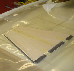
On the right, you can see one of the core pieces, cut from 3mm Rohacell with 3mm carbon rods tacked to the leading and trailing edges with cyanoacrylate. These rods are actually kite spars, available from Into The Wind, which is a great source for this kind of thing.
The kite spars provide a solid finish for the leading a trailing edges of the fins, which would otherwise be the soft edges of the Rohacell core. (Here the masking tape holding the spars in place for the CyA has yet to be removed.)
Note the rectangular area at the bottom, which will form the tab for to-the-motor-tube mounting. The carbon rod edges don't extend to this area, as they will butt against the outside of the aiframe.
Step 2: Core Reinforcement
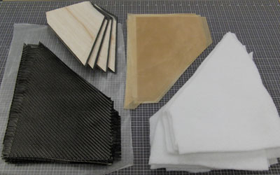
One layer of 5.7oz plain weave carbon fiber cloth was laminted to each side to bond the edging to the core and provide the stifness necessary for the core of the fin. The picture below shows the materials used for laminating the cores.

Of note here are the materials for vacuum bagging. Since these are flat layups, they are used with a base board. The base board is mainly used to keep the parts flat while the epoxy cures. I prefer ½" Acrylic for the board itself and cover it with non-porous Teflon release fabric.
To wet out the cloth, I painted epoxy on the core blanks, then applied the carbon fiber cloth and finally painted more epoxy into the cloth to fully saturate it. Excess epoxy is removed by the vacuum bagging process; it migrates through the release fabric and into the heavy breather.

After the fabric was wet out, the cores were placed into the vacuum bag. In this case, I'm actually using a veneer press made by Quality VAKuum Products. It's easy to see the fin shape as the the bag presses down and tightly squeezes the lamination to the core.
When the epoxy reaches the "green" or "leather" stage, I remove it from the bag and use a hobby knife to trim off the excess. This saves a lot of sanding because if you catch the epoxy at the right step, you can cut through the partially-cured reinforcement easily. One way to keep track of the epoxy cure progress is to paint a scrap of cloth with left-over epoxy and keep it outside the bag.

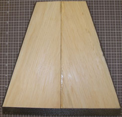
On the left, above, is the core after cutting away the excess cloth with a hobby knife. On the right is the blank after the ends of the rod have been trimmed and the edges have been sanded. Even at this point, with only two layers of carbon fiber, the fin is incredibly stiff. The Rohacell core separates the two layers of reinforcement, creating a truss structure that is enormously strong and stiff for its weight.
Step 3: Balsa Profiles
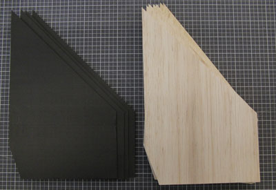
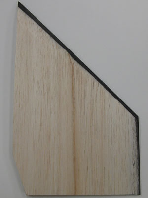
To create the compound angled Nike fin profile, I used balsa wood. Balsa is light and easy to shape, even with hand tools. In fact, it sands so easily that you have to be careful not to overdo it! For the Nike-Asp booster fins, I used pre-milled shapes and sanded them after bonding. That worked fine, but for these fins I tried another technique for forming the profiles.
The Nike fins have a compound taper: they are thinner at the tips than the root and taper from the center to the leading and trailing edges. I needed to create a block with a trianglular cross-section that would form each half of each side of the profile.
This time, I decided to try using a surface planer. In order to support the delicate balsa through the planer, as well as create the necessary angle, I built a jig.

Above you can see one end of the jig (or "sled"). it's basically just a 1" piece of flat stock with a runner underneath to create the angle and a lip to keep the balsa blank aligned. The runner is a bit hard to see, because I covered it with aluminum tape, but it is formed from a ¼" thick piece of stock and glued to the bottom of the sled. The lip is on the low side, which will be the thicker side once the balsa passes through the planer.
As it turned out, these blanks were about 5½" wide so I ended up gluing together two 3" wide pieces of balsa stock. (The reduce waste and use up some stuff I had laying around, different thicknesses were used for some of the blanks as you can see above.)
The planer technique was moderately successful. I got the blanks I wanted, but the softness of the balsa wasn't really up to the ferocity of surface planing. About a third of the resulting blanks were unusable because they were crushed or splintered. I also had a big mess of wood shavings to clean up afterwards.
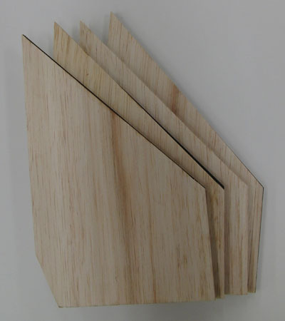
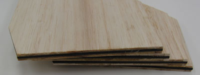
Once the triangular stock was formed, it was a simple matter to cut the profiles from it. I used a full-sized template to cut each quarter profile from the stock. Balsa is easily cut using a hobby knife, but be sure to put in a new blade so you get a clean edge.

Here you see the two stacks of completed profiles. Note that they are two different shapes, which are mirror images. The grain runs along the leading/trailing edge showing how the edge that tapers down to nothing runs along at that point. This automatically creates the correct taper from root to tip at the centerline of the fin.
Once the profiles were formed, it was a simple matter to bond them to the cores. The faces of the cores were first sanded, then I painted a thin layer of laminating epoxy onto the balsa profiles and taped them in place on the cores.
 |
 |
In the photo above left, you can see the fin again in the vacuum bag. (This time, I am not using a base board since the part is no longer flat.) On the right, the part has been removed from the bag and the masking tape is gone. We now have a fin with a proper Nike-style profile.
Step 4: Surface Reinforcement
To complete the fins, another layer of carbon fiber was laminated onto the profiles. Balsa is quite soft and some skin is required. The fins were already quite stiff, but another layer of carbon fiber made them truly unbendable.
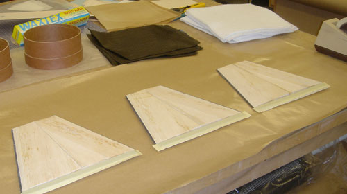
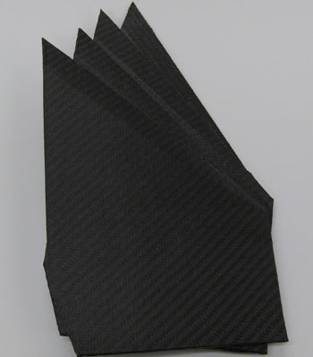
Here you can see the materials laid out for laminating the skins on three of the fins. (Fin production as actually staggered out over several days so that I could demonstrate parts of the process in the two seminars I held in April 2007.)
Once again epoxy was painted onto the profiles, the carbon fiber cloth was applied and then fully wet out. The parts then went into the vacuum bag for a third and final time.

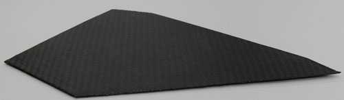
And here we have the finished fin. Once again, the excess cloth was trimmed off and the edges sanded smooth.
Note how the center line is clearly defined (where the quarter profiles meet). You can also see some of the balsa grain showing through the the cloth.
At this point, the surface is the carbon fiber reinforcement. After the fins are mounted to the airframe, they will be covered tip-to-tip with fiberglass. That will bond them firmly to the airframe as well as provide a layer for filling and sanding to create the final surface finish.
Booster Airframe
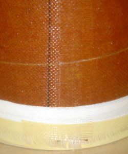
In order to get the proper outer diameter for the model, I decided to use 7½" phenolic coupler tubing for the airframe (giving me a finished 7½" O.D.). Giant Leap sells coupler tubing in the same lengths as airframe tubing, so getting it was no problem.
After cutting the two sections of tubing to length, the first step was to reinforce them with fiberglass. Note that I say "reinforce" here in the sense of giving them a hard skin rather than being necessary for flight-worthiness. The reinforcement was done using a simple technique that gives me good results for various sized tubes with a minimal amount of time and fuss.
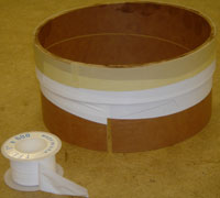
The key to this technique is to use "end caps" when skinning the tubes. If you don't have somewhere for the excess cloth at the ends to go, it gets in the way when rolling the tube and the ends always get messed up. To make each end cap, bond a short section of coupler inside a sliver of airframe tube. (My aiframe tube was itself coupler so the "coupler" in this case was cut down and you can see the left-over slot.)
To prevent the end cap from getting bonded into the tube, I cover it with Teflon® tape. As the end cap is inserted into the tube, some of the Teflon bunches up and forms a dam between the tube end and the end cap.
Above you can see one end of the tube ready for reinforcement. Things to note:
- The outside of the tube is well sanded and wiped down with alcohol.
- The end cap is firmly seated so that there is no gap for epoxy to seep into.
- A line has been drawn down the length of the tube for aligning the cloth.
- The cloth has been neatly trimmed and squared.
"The" secret to working with composites is to keep things clean and be prepared before you mix the epoxy. Below you can see the cloth laid out in preparation for wetting out. I've used paper to protect my work surface and taped it down securely in the back and on the sides. (This paper is a key part of the rolling process as described below.)
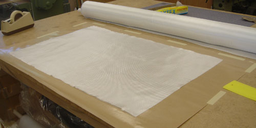
Mix up laminating epoxy and pour it onto the cloth. Use a squeegee to spread it out and fully saturate the cloth and to remove excess epoxy. (You want the cloth to turn transparent, showing that it's thoroughly saturated, but also to remove any puddles of epoxy.)
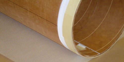
Once the cloth is wet out, it's time to roll the tube. In this case, "roll" is exactly the right word. Rather than trying to move the cloth, which will inevitably cause a mess, we leave the cloth flat and roll it onto the tube.
Place the tube onto the cloth so that the line on the tube hits the front edge of the cloth. Lift the front edge of the paper up and roll back a little, smoothing the cloth onto the tube through the paper. Once the cloth edge is up about 90° from the table, carefully peel back the paper and smooth down the cloth. (Be careful with the cloth at this point since the cut edge is fragile.)
Roll back a little more until the edge of the cloth is 180° from the table (on top). Now comes the "stretch and smooth" part, which will keep the cloth tight to the tube and remove any excess epoxy. Using your gloved hands, work the cloth towards the tube ends and slightly towards the top. Don't use excess force, but you should feel the cloth stretching a bit and the epoxy working evenly through it.
Now, grasp the end caps and rotate the tube away from you while pulling the whole thing toward you. This will cause the cloth to stretch more around the tube circumference due to the friction between the wet cloth and the paper on the table. (Remember that we taped the paper down to the table.) Rotate/pull about 1/8 of a turn then do another round of smoothing/streching out to the sides. Keep rotating/pulling and smoothing/streching until the entire tube is wrapped. Et voilá, a perfect lamination!
 |
 |
Check your tube for shiny patches and damp off any excess epoxy with toilet paper. Once the epoxy reaches the leather stage, run an X-Acto® knife between the end of the tube and the end cap. This will give you a perfect edge to the lamination, right at the end of the tube. You can also pop out the end caps and clean them off at this point.
Here are some of the key things in this technique:
- Cut the cloth 1" wider than the tube; the excess will go onto the end caps.
- The end caps support the cloth past the end of the tubes.
- Once the cloth is wet, don't try to move it.
- The end caps give you handles to turn and pull the tube when you roll.
- Smothing and stretching the cloth as you roll is key to removing bubbles.
I used 6oz. fiberglass for this lamination, but the same technique works with other types of reinforcement. (I've done exactly the same thing with carbon fiber and Kevlar® laminations.)
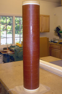
Finally, the tube was slotted using my trusty fin slotting jig the the complete fins installed through the wall and to the motor mount.
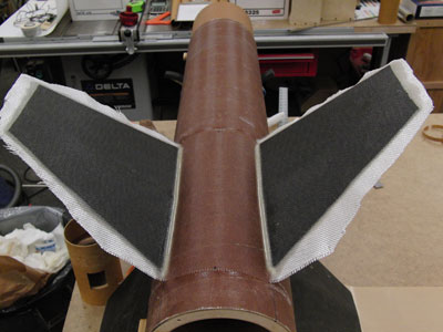
In the photo above you can see the last step of tip-to-tip reinforcement with fiberglass. If you look carefully, you can see the healthy fin fillets perfectly shaped using my nifty spoon technique. (Yes, my shop is always a bit messy, but this picture actually makes things look worse than they are.)
Interstage Coupler
In any multi-stage rocket, the interstage is a critical part. I had decided to size the rocket based the sustainer being a 98mm minimum diameter airframe. In fact, an AeroTech case would be used for coupling. By hanging the motor from the aft end of the sustainer, it sockets into a section of airframe in the interstage.
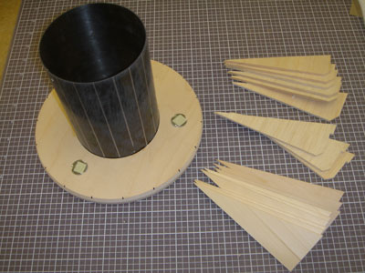
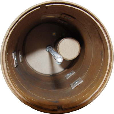
This meant that I needed to support a tube for the motor to socket into at the top of the booster as well as form the double-cone shape of the Nike-Tomahawk interstage. The core of the interstage is two parts: a custom bulkhead and a section of tubing. The bulkhead is 8" O.D. and has a groove to mate with the forward end of the booster one on side and with the aft end of the socket tube on the other. (It also has 3 T-nuts mounted into it for the booster electronics bay.)
The bulkhead also has two bevels formed into the outer edge, one that matches the conical transition from 8" to 4" for the forward end and one that matches the transition from 8" to 7½" for the aft end.
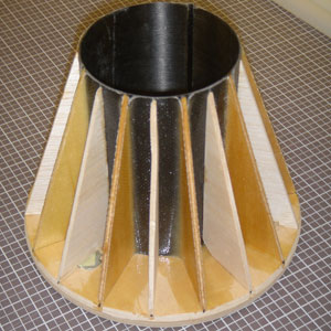
To form the conical shape where the interstage reduces to the sustainer diameter, I decided to use a set of ribs with fiberglass reinforcement. The picture above shows the socket tube in the bulkhead and the individual ribs.
Half of the ribs are basswood and half are balsa (9 of each). The nine baswood ribs we tacked in place with cyanoacrylate, then the inside corners were bonded with thick epoxy.
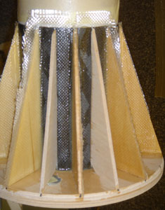
Then fiberglass was laminated across the socket tube and facing sides of each pair of ribs. This basically created nine fiberglass-reinforced bays helping to support the socket tube and prevent it from deflecting to the side under thrust.
Finally, the balsa ribs were placed on the wet fiberglass in the center of each bay to help define the shape (but not provide any additional support).
The picture on the right shows the fiberglass wrapped into two of the bays and the two balsa ribs applied afterwards. (I did only two bays at a time to avoid having to rotate the part while working on it.)
Once all the bays were reinforced and the epoxy had set, the excess cloth was sanded off. Finally, I decided to cut a slot into the sleeve tube to accomodate an igniter fed from the sustainer. (I am hoping to put together some sort of forward-end ignition for the sustainer, but failing that that, I can always use the traditional method.)
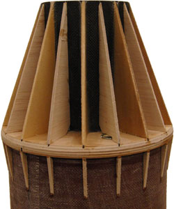
Then came the mounting of the interstage to the forward end of the booster. In the picture to the right you can see the core mounted to the airframe tube and matching ribs mounted to define the conical transition from 7½" to 8".
Next comes creating the skin for the interstage. First of all, I made skins for two cones from heavy paper and tacked them to the ribs using 3M spray adhesive.
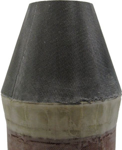
Then, they were covered with fiberglass to create the hard shell. (The larger forward cone ended up needed a layer of carbon fiber as well to be stiff enough.) The paper turned translucent when the fiberglass was applied, so I'm taking this as a good sign that the epoxy soaked through the paper and created a good bond to the underlying wood ribs.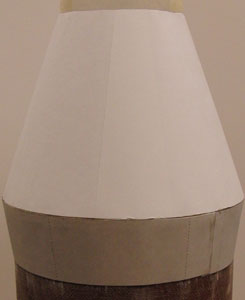 |
 |
Booster Electronics Bay
The booster has a generous amount of space inside since the tubes are so large. However, I wanted to leave as much space as possible for the motor and for recovery so the electronics bay is just over 5" tall. (the G-Wiz MC2 is just under 5" tall.)
So the bay is a pretty traditional design with accomodations for two G-Wiz units and four batteries. Because I wanted the bay to be squat (since there was a large diameter and I wanted to maximize the length of the recovery area), I mounted the four 9v batteries right on the bottom (removable) bulkhead.
 |
 |
Above you can see a view of the front, showing the battery mounting and the power switches along with the board to which the G-Wiz units will be mounted.

Here you can see the view from the bottom with the Rouse-Tech CD3 unit installed using my home-made wooden holder. This was a built a long time ago, my holders have gotten a lot more sophisticated as you can see in the sustainer electronics bay below.
Tomahawk Sustainer Fins
Like the booster fins, the sustainer fins also have a complex profile. However, instead of the common Nike fin profile, these have a taper from root to tip as well as a beveled leading edge, which was produced by bending these fins from sheet metal on the real Tomahawk. A good challenge! (See the overall drawing for more detail on the fins.)
Because the sustainer can potentially fly very fast and for a long time, I wanted the fins to be rock-solid. So, I started with carbon fiber plate as the center of the core. The profile would be formed using balsa again, but I wanted the covering carbon fiber skin to be bonded directly to the carbon plate, so the balsa thins to nothing at the leading and tip edges.
Here you can see the parts of the core: four centers carbon fiber and eight thickeners of balsa.
Above you can see two views of the initial fin cores after they came out of the vacuum bag. A layer of balsa sheet has been laminated onto each side of 2mm carbon fiber plate. The next step was to sand into the balsa to form the profile.
Hopefully this picture is worth a thousand words, so we can get by with a couple of sentences of explanation. I made a jig that held the fin with the carbon plate horizontal. One side of the jig (root edge) had a higher wall than the other (tip edge), so that when I ran a sanding block across both of them, the taper was created. Note how I've sanded so that very little balsa is removed at the root and the balsa is completely removed at the tip.
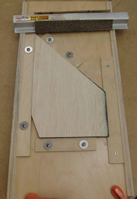
The bevel was much easier since I was able to use my standard fin beveling jig. The only wrinkle was that I had to make a sled to hold the fins so that the bevel would come out correctly so that:
- The tip of the leading edge was a knife edge for the full length,
- The bevel at the root edge with 1¼" deep and
- The bevel at the tip edge with ¼" deep.
(It's a bit hard to see how the bevel changes width from the root to the tip in the photo.)
Finally, the fins needed to be skinned. Above is the standard panoply of pieces in preparation for vacuum bagging. Since these are small fins, I used the trusty FoodSaver for these.
It's a bit easier to see the taper and bevel in this pair of photos, although the black of the carbon fiber requires a better photographer than I. (The bottom photo is a three-quarter view with the leading edge along the bottom.)
Sustainer Airframe
The sustainer airframe would be minimum diameter for 3.9" motors, which actually determined the 45% scale of the whole model. This makes a good-sized rocket, and also gives me a chance to use up some of the carbon fiber tubing I'd had laying around.
No work was required to fabricate the tubing, and cutting is relatively simple using a diamond blade in a bench-top table saw.
Sustainer Ignition
The sustainer contains the electronics for staging (second stage motor ignition), in a dedicated electronics bay immediately forward of the motor. This basically occupies the space taken up by the "backward ejection" coupler.
I decided to make my own head-end ignition system. See the forward igniter page for more info.
The basic idea is to mount everything to the forward end of the of the sustainer motor. This isn't an unusual method of retention and is idea for transferring the weight of the heaviest part of the rocket to the parachute rigging, but is a little more tricky here.
First of all, the forward closure has been modified for the forward igniter so I had to work around that. I cut a short section of 2" x 1" aluminum tube to act as a bracket to connect the forward closure to the recovery system via a threaded rod. This tube also had four holes drilled and tapped to support the mounting board for the AeroTech Electronic Forward Closure (EFC) which powers the igniter.
 |
 |
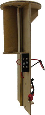
In the pictures above you can see a long view of the bracket and threaded rod connected to the forward closure on the left. On the right, is a close-up of the bracket.
 |
 |
Here is a side view showing how the EFC is mounted and connected to the glow plug. On the right is the sustainer airframe slid down onto the motor/closure/mount and secured with an eye bolt. Retention is positive and the weight of the motor is transferred to the parachute bridle through aluminum threaded rod to the bracket and to the forward closure.
The small hatch is just enough to reach in and turn on the EFC, as well as verifying the continuity and program through the LED below the battery holder. (This hatch will be covered by the forward airframe while in flight.)
Sustainer Electronics Bay
There is 10" of space for the sustainer electronics bay. This sounds like a lot, but a 4" airframe doesn't leave much space. I wanted to get a lot of stuff in here too, including a camera, but didn't manage to fit it all. However, I did fit two full-size G-Wiz altimeters and two Rouse-Tech CD3 units!
Above is an inside view of the coupler which contains the electronics bay. The bay assembly slides into the coupler section so the bay itself just has the forward bulkhead and the plate mounting the electronics and batteries.
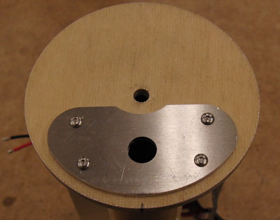
In the picture above you can see a view from the top (forward end) of the sustainer electronics bay. The aluminimum plate is the mounting for a CD3 unit for the main parachute deployment.
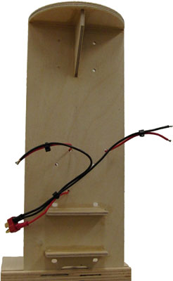 |
 |
And above you can see the front view and side/rear view of the bay itself. The wiring harness and power switches are installed and the bay is ready to go. The section of tube at the top matches one inside the coupler (at the bottom) and both contain the CO2 cartridges used with the CD3 units.
Historical Info.
Text and picture from Rockets of the World.
The Sandia Corporation created Nike-Tomahawk to loft 100lb (45kg) Atomic Energy Comission (AEC) payloads to an altitude of 200 miles (320km). The first Nike-Tomahawk flew on July 25, 1963 from Tonopah, Nevada. Its AEC solar physics payload succeeded in measuring the sun's X-ray output. NASA began flying the Nike-Tomahawk in 1965, with the launch of flight 12.05 GA (also called 18.01 GA) on March 19, 1965.
In September of 1966, the Nike-Tomahawk took part in a program in the study of the Earth's magnnetic field and the electric fields in the upper atmosphere. NASA's Langley Research Center joined forces with the West Germany's Max Planck Institute in the launch of a pair of barium vapor release payloads. Barium was selected as it would both ionize (lose electrons to become charged) and glow in sunlight. The first rocket was a Javelin, launched on September 24; the second was a Nike-Tomahawk launched the next morning.
It was still dark at 5:51 AM (EDT) when NASA Nike-Tomahawk 18.26 IA lifted off from Wallops Island. After the 3 second burn of the Nike booster, the upper stage coasted for about 9 seconds before igniting. The tomahawk then burned for 9 seconds, boosting the payload up into the sunlight. Even as the upper stage burned, the first small 1 lb (413 gram) tracer cloud blew out of a canister at the base of the payload. At about 167mi (268km), 25 seconds after launch, a pair of larger containers released a second, 22lb (10kg) cloud. The payload then passed its apogee of 124 mi (280km), and release a third cloud (again 22lb or 10kg) at an altitude of 160 mi (256km), 39 seconds after launch.
The canisters aboard Nike-Tomahawk 18.26 IA did not hold pure barium. Copper oxide in the mixture chemically reacted with some of the barium (in an analog of the high-temperatue thermite reaction) to produce the heat to vaporize the rest of the barium. In the intese heat of the reaction, strontium carbonate in the mix decomposed carbon dioxide (CO2) and strontium oxide (SrO). The CO2 gas forced the cloud material out of the canister, while the SrO in the cloud glowed without ionizing, producing a neutral component of the cloud. Observers at Back Bay, Coquina Beach, and Wallops Island photographed the ionized and neutral clouds with an assortment of cameras.
While the neutral strontium clouds expanded in all directions, the ionized barium clouds were confined to the Earth's magnetic field lines. By trianguating the observations from various sites, NASA and Max Planck researchers mapped the exact orientation of the field in three dimensions. As time passed, the illuminated field lines began to drift. This effect was a result of electric fields in the upper atmosphere. Max Planck researchers were able to calculate the magnitude of a westward electric field from this drift.
The US-German project was a successful test of a technique to be used systematically ever since. The Nike-Tomahawk is also a continuing success. Over 300 have been flow to date, more than 220 of which were launched by NASA.
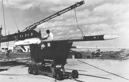
Nike-Tomahawk 18.26 IA is prepared for its night launch.
(NASA photo courtesy Robert Biedron)