Just Married!
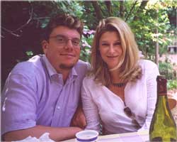
On September 27, 2002, my lovely wife Renée and I were married in Burlingame, California.
 Early on she suggested that I build a "just married" rocket and we could
show it off at the wedding and then fly it together at the next launch.
What an idea and what a great woman!
Early on she suggested that I build a "just married" rocket and we could
show it off at the wedding and then fly it together at the next launch.
What an idea and what a great woman!
The next major launch after our honeymoon was the November ROC-stock, hosted by the Rocketry Organization of California (ROC) at Lucerne Dry Lake in So. California. Given the ROC tradition of Magnum drag races, I decided to build a Loc/Precision Magnum and Renée and I could enter it into the drag race together.
As it turned out, ROC-stock was blown out (there were 45mph dust storms on Lucerne Dry Lake!) so instead we got to launch the rocket at the AERO-PAC Mudroc launch in June 2003.
The Pictures
 |
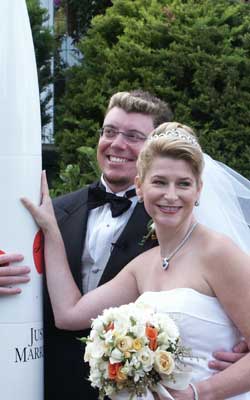 |
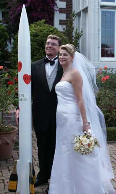
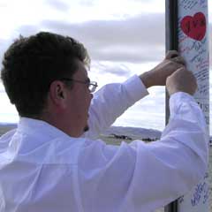
Here we are on the wedding day, posing with the rocket! Several friends suggested that we let people sign the rocket instead of a traditional guest book at the wedding. (These are the last shots of the rocket before it was signed and were taken by Phillip Coker.)
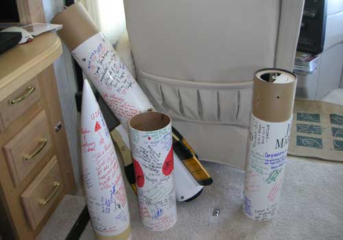
Even after 9 months, the rocket was still in almost perfect condition when it arrived at the Black Rock Desert. Above you can see it as I'm getting ready to prep it on Friday evening. I decided to fly it on a K550 since I didn't want to risk the rocket.
|
It took about two hours on Friday night to prepare the electronics and do the
last-minute setup.
On Saturday morning, we brought the rocket out to the pad and set up it.
As you can see it was a beautiful morning with almost no wind.
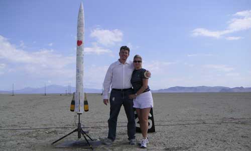
The design of splitting in the middle for arming worked out well. On the right you can see me fastening the sections together with 4-40 screws after arming the electronics and sliding the sections together. Below is the obligatory "dumb rocket picture," but this time with my wife!
|
|
I missed taking the usual liftoff sequence since I had the camera set incorrectly, but video of the flight is coming. The flight was perfect and with no wind and dual deployment, the rocket came down almost on the range in perfect shape.
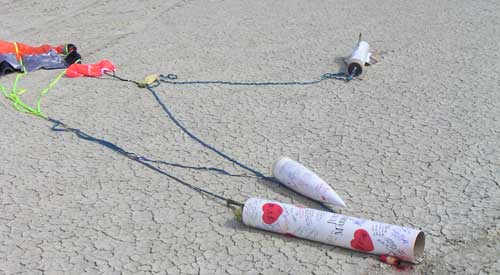
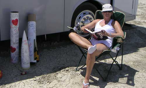
The flight went to around 3500 feet (3456 by the G-Wiz and 2525 by the R-DAS). Below you can see Renée relaxing next to the recovered rocket. We both breathed a sigh of relief that it came back safely!
|
|
Mike Brest took a great video of the entire flight and Jamie Clay converted it to an AVI for us all to enjoy. |
The Kit
The Magnum kit is one of Loc/Precision's larger kits with 5.5" diameter tubes and an overall length of 83½". Despite the size, the Magnum is very much a model rocket-style kit. The tubes are paper phenolic and it's basically just a big tube with a motor mount in one end. For this incarnation, I decided to start with the Magnum-3 kit (76mm motor mount and G-10 fins).
Like my previous Magnum, I decided to modify the organization, but maintain the same overall dimensions. Mainly, I wanted to include:
- electronic dual deployment,
- a zipper-less design and
- custom-shaped fins.
I made the booster section 28" long (long enough for a 32" motor, which will even accommodate an M1315). The payload section then is 34" long and split in the center for access to the electronics bay.
Of course, I also made other changes like reinforcing the couplers and airframe tubes. The Loc/Precision airframe tubes are quite stiff, even though they're paper, However, the couplers are not. Loc/Precision now sells "the Stiffy" which is an insert tube for a coupler. The Stiffy does add stiffness and strength, but it's very thick and heavy and isn't a perfect fit into a coupler. For more information on the custom aspects of this rocket, see:
- Reinforced Couplers, carbon fiber-reinforcing the Loc paper couplers;
- Custom Fins, custom-made thick fins with a champagne bottle outline;
- Electronics Bay, a different style of electronics bay with a hatch;
- Reinforced Tubes, vacuum bagged fiberglass for airframe tubes.
As usual, I also painted the rocket with automotive paints for better color choice and durability. Following the Magnum (with the addition of white) the PPG DBU colors are:
| body | DBU91046 | White |
| bottle | DBU43848 | Green |
| label | DBU83467 | Cape-town yellow |
| foil cap | DBU27382 | Gold metallic |
Most of the rocket is plain white. The bottles on the fins required the the other three colors. I used the Diamond Coat clear for a harder finish.
The painting was done in a rush right before the wedding. The clear coat went on just before midnight on Wedensday, September 25 and the decals were applied on Friday morning. I guess nothing would get finished without deadlines!
|
One nice thing about cardboard rockets is how light they are.
Even with the fiberglass reinforcing, the rocket came out much lighter
than most rocket of this size: 11lbs dry!
Note that this includes the structural parts of the rocket, but not motor or recovery system. The booster weight includes an adapter from 76 to 54mm (as it will fly at ROC-stock). |
Reinforced Couplers
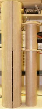
I decided to reinforce the inside of the couplers with carbon fiber. My usual method is to use a balloon inside the coupler to hold the cloth against the coupler walls and press out excess epoxy. Bill Farr suggested using vacuum bagging by pulling the bag back through the inside of the coupler. Since I needed two couplers reinforced, I decided to compare the two methods.
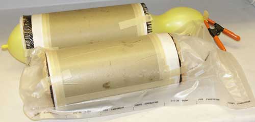
Above you can see the two couplers with the carbon fiber laid up and using the two methods of pressing the reinforcement. Notice how the coupler in front has the FoodSaver® bag looped back through the inside of the coupler. Also note that the coupler in back has the punching bag balloon bulging out both ends. (Also, it's important to cover the outside of the couplers with paper so that they don't end up with epoxy fingerprints.)
I was worried that folding the vacuum bag back inside the coupler would cause wrinkles. The problem is that there is no good way to smooth the inside of the bag during the short time the vacuum is being drawn. There were lots of wrinkles, but they don't seem to have transferred to the reinforcement inside the coupler.
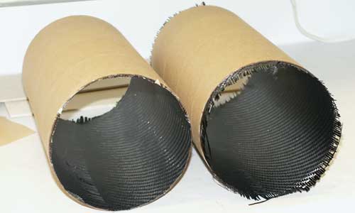
In the picture above, the coupler on the left was vacuum bagged and the one on the right used the punching bag balloon. (It's easy to tell because the vacuum bag crunched up the excess carbon fiber cloth at the ends of the coupler.) The important thing is that in both cases, the reinforcement is pressed against the walls of the coupler and excess epoxy has been removed.
Both couplers feel about the same in terms of stiffness, but the vacuum bagging clearly removed more epoxy than the balloon. The vacuum bagging method is a success!
Custom Fins
The fins were the next project. I wanted to do something fun and different for the fins and we decided to make them look like champagne bottles. We will be serving Veuve Clicquot champagne at the wedding so it made sense to do three bottles of these on the rocket.
In the drawing to the right, you can see the bottle and its outline (including the fin tab) for the fin cutout.
Also, the dotted line is a simplified outline used for simulation purposes. (The area below the dotted line is the tab to the MMT.)
The bottle is full size, with a little space left between the rocket body and the side of the bottle to create a little more fin area. You can download the PDF drawing (full size) for details.
The original Magnum kit fins were not going to be used at all. (They are G-10 and the wrong shape.) Needing to build composite fin blanks and cut out the bottle shape, I was able to try out the Rohacell® closed-cell foam sheet.
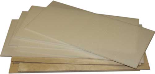
In the photo above, you can see the core material for the three fin blanks. Each fin would have a piece of 1/8" plywood in the center with two pieces of 3mm (1/8") Rohacell on each side. (This comes out to about 3/8" which is the thickness of the regular Magnum plywood fins.)
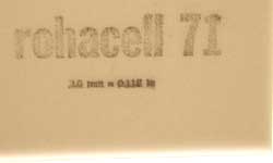
The Rohacell has some very nice properties for composite layups. It's very light, but has a consistent structure and good density. It is made of closed-cell foam with small cells. "71" refers to the density. It also comes in 31 and 51 variations, which are lighter.
I wanted to round the edges of the fins to give a bit of the roundness of the bottle. The extra Rohacell layers added thickness without much weight. And the extra layers of carbon fiber added stiffness as a layer was used between each layer of core material and on the outside surface (4 pieces of carbon fiber reinforcement in total).
 The next step was to glue up the fin core blanks using the plywood, Rohacell and carbon fiber.
The drawing on the right shows the composition of the fins when complete:
a central piece of 1/8" plywood, two inner carbon layers,
two pieces of 3mm Rohacell 71 and two outer skins of carbon fiber.
The next step was to glue up the fin core blanks using the plywood, Rohacell and carbon fiber.
The drawing on the right shows the composition of the fins when complete:
a central piece of 1/8" plywood, two inner carbon layers,
two pieces of 3mm Rohacell 71 and two outer skins of carbon fiber.
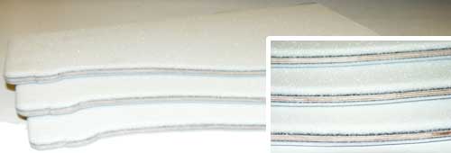
In the picture above, you can see the fins cut out from the inner layers (everything but the outer carbon fiber skin). The white Rohacell is a little hard to see, but the edges of it are rounded over to create the fin edge profile.
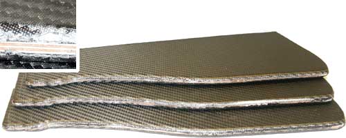
And here they are covered in carbon fiber and ready to be installed in the rocket.
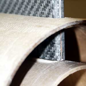
On the right, you can see the first fin bonded to the motor mount tube. (The fins fit tightly into the fin slots so they will stay aligned during cure.)
At this point, just the root of the fin was bonded to the MMT. The next step is exterior fillets and tip-to-tip fiberglass. Fillets were applied to root edges of two fins adjacent to a section of tube.
Once these had partially cured, a wrap of 6oz. fiberglass cloth was applied. First one side of the each fin and the body tube between them was painted with epoxy. Then the glass was applied and smoothed down onto the surface, paying special attention to the fillet area. Finally dry spots were wetted out and excess epoxy was blotted up with toilet paper.
The pictures below show the first bay with the fillets only and then with the fiberglass reinforcement.
 |
 |
Finally, the interior of the fin can was filled with two-part expanding foam and the rear centering ring installed. The two-part foam fills the cavity, but more importantly, is itself a very strong adhesive and replaces internal fillets of epoxy.
Electronics Bay
Lately I've been making self-contained electronics bays that a prepped outside the rocket and then slide into the payload tube. This works well because it's easy to prepare, but is not ideal for electronics that use LEDs for status because you can't see them once the rocket is on the pad.
For this rocket, I decided to build the payload tube in two 17" sections which would be screwed together during flight. The electronics bay is bonded to the lower part of the payload tube (which forms the drogue recovery area). The upper payload tube slides onto, and attaches with screws to, the electronics bay coupler. This allows room for a hatch in the side of the coupler.
Once the rocket is loaded onto the rail, the forward section can be slid upwards a bit to turn on and check status of the electronics. Then, the section is slid back into place and screwed on for flight. This design also removes the necessity of an external switch.
In the image above, you can see a drawing of the electronics bay, both side and top view (with the top cap removed). You can also download a complete drawing of the overall rocket and the electronics bay in detail. Note that the electronics mounting plate (shaded large rectangle) removes from the top of the bay, allowing easy access for prepping the electronics. (The hatch is solely for arming and checking status.) For even more detail on the cut-out rings (above right), download the drawing.
 |
 |
|
 |
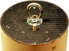
The pictures above show how the bay looks. Along the left is the bay from the front, showing the hatch and the top fixed ring with the cutout. Note also the slots on the left and right side of the cutout for the electronics mounting board.
Top right is the same view, with the removable cover installed and the eye bolt screwed on. This bolt both secures the top and provides an attachment point for the main recovery bridle. (The dowel in front of the eye bolt is a small handle used to pull the top off once the bolt is unscrewed.)
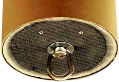
Bottom right is a view of the bottom of the bay. The bottom plate is solid and fixed and the eye bolt is not removed. In fact, this part of the bay will be epoxied into the bottom half of the payload section. (The two small holes are for ejection charge wires.)
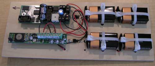
And above you can see the board with the electronics and batteries mounted and ready to connect to the charges. Note that the G-Wiz uses two batteries (using separate connectors) and I set up the R-DAS Kompact to use to 9v batteries wired in parallel since it is so power hungry.
Reinforced Tubes
The tubes were reinforced with one layer of 6oz. fiberglass. (Mostly to give them a hard surface since the paper tubing is a bit soft.) I used my usual technique of vacuum bagging with the FoodSaver®. (See my Kitchen Table Vacuum Bagging page for more info.)
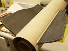
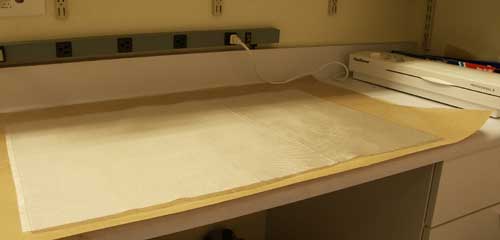 1. The fiberglass cloth laid out in preparation for rolling up the tube.
|
||
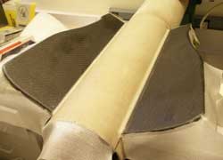
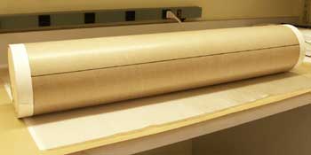 2. The tube (with end-caps) ready to roll up in the fiberglass cloth.
|
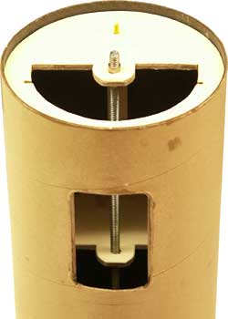
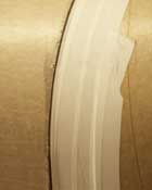 3. Close-up of the end cap.
|
|
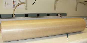 4. Tube out of the bag and end caps removed.
|
 5. Close-up of tube surface.
|
|
This sequence shows the steps in laminating the 28" booster section:
|
 6. Booster tube filled and sanded (and slotted) with MMT.
|
The three tubes were all done using this method. One 28" booster airframe tube and two 17" tubes that make up the payload section, which breaks in the middle. (Download the PDF drawing to see the airframe layout.)