Forward Igniter
Our normal means of lighting a commercial solid propellant rocket motor is using an electric match as the primary initiator. This appears to be the only option, given that the safety codes require "reliable electrical ignition" (i.e., no fuses or other pyro initators).
The electric match is used to ignite a secondary charge, made up of a "pyrogen mix" including metals, black powder, "thermite" or slivers of more easily ignited propellant (AeroTech's Blue Thunder propellant is a favorite). This secondary charge actually burns long enough to ignite the top motor grain and begin the motor burn.
This system works well and has been refined by various rocketeer over time who have chosen their favorite mixtures and methods. It does have one logistical issue: the igniter must be fed through the nozzle (aft end) of the motor up to the top grain. This is usually done by taping the glob of ematch and secondary charge to a thin wooden dowel, giving rise to the name "lollipop igniter".
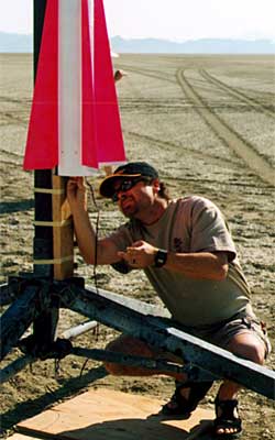
On the right you can see Gary Rosenfield installing a traditional lollipop igniter into the "Pegasus fin motor" used in the second stage of my Nike-Asp.
This all works fine for igniting the first stage, since everything is on the ground and still until after the motor lights. It gets a bit more dicey for igniting the second stage, since the thrust of the first stage can disloge or otherwise disrupt the lollipop igniter.
Things are even more difficult for minimum diameter second stages. Here one must choose between ignition via electronics in the booster (which means losing the opportunity for a staging delay) and via electronics in the sustainer (which means running wires outside the airframe).
Head-End Ignition
The best way to ignite sustainer motors is via a "head-end initiator." This screws the initiator into the forward end of the motor case, which means that there are no wires to run through the core and out the nozzle. It also means that the initiator can be easily triggered via electronics located in the sustainer without worrying about wiring alongside the MMT or outside the airframe.
Commercial hobby rocket motor manufacturers don't provide head-end initiator capability for various reasons. Among those reasons is concerns about safety, since the traditional lollipop igniter is normally installed after the rocket is out on the pad. (This argument is weaker for multi-stage rockets of course.)
My Nike-Tomahawk has a minimum-diameter second stage, which put it squarely into the category of configurations least well served by lollipop igniters. Time to come up with a different solution!
This page describes how I modified an AeroTech 98mm forward closure for forward ignition by using a model airplane glow plug as the primary initiator and a custom part to direct the secondary charge properly to ignite the motor.
Tom Rouse and I worked on this design and he generously provided a forward closure and modified it for me. Rob Briody helped me with electronics consulting related to using glow plugs. Nice building and flying with you guys!
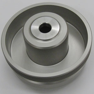
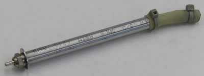
On the left you can see the key part which solves the main problems
(download the drawing in PDF format):
|
Glow Plugs
Model airplane glow plugs are key because they solve the problem of maintaining an electrically-fired primary initiator, while still providing a gas-tight seal with the closure. This is due to their being threaded, which allows sealing via an O-ring or brass washer. The forward end of my igniter has a hole with a ¼-32 inside thread to accomodate a standard glow plug.
However, glow plugs introduce a new problem as well: they require a high current (up to 4A) at a low voltage (around 1.5V, never exceeding 2V). This doesn't match our usual electrical power source for rocketry electronics based on 9V batteries. The current is less of an issue as we can use higher-current batteries, but the voltage must be dropped under 2V continuous or a higher voltage must be pulsed.
Actually, I originally got the idea for using a glow plug as the primary initiator from the AeroTech Electronic Forward Closure (EFC). It turns out that this provides pretty much the same electronics one needs for staging: it fires the output a given amount of time after motor burnout.
Normally, the EFC screws onto the forward motor closure and fires the glow plug into an ejection well attached to its forward end. In my case, I needed to reroute the glow plug to be aft of the EFT, at the forward closure of the sustainer motor. (The EFT uses a G-switch to detect motor burnout so its orientation cannot be changed.)
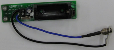
Above you can see the EFT with the forward ejection charge well and original glowplug removed. Doing this requires no irreversible changes to the EFT as the board screws to the ejection charge well and the glow plug uses a terminal block.
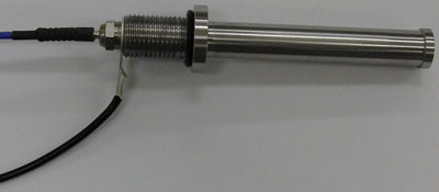
And finally you see how the glow plug screws into the igniter. The tip connector is a standard R/C glow plug part and the body connector is just a ring terminal.
Closure Modification
Here's the scary part: making a modification to the motor case. In order for the igniter to pennetrate the motor case, we need to drill a hole to accomodate the threaded forward end of the igniter.
Here you can see the closure ready to go. Note that the forward-most part of the closure has been removed (the part that contains the inside thread for motor retention). This leaves about ¼" of thickness between the forward surface and the bottom of the delay charge well.
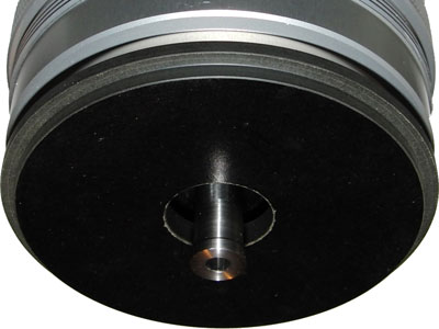
And finally here's the forward closure, with the delay charge spacer (hidden), and the forward seal disk. This shows how the tip of the igniter peeks through the liner and places the secondary charge inside the bore of the top grain. Note that this closure has a 2" deep delay charge well, so the igniter will work even with the "extended smoke charge" style closures.
Secondary Charge
The secondary charge is placed inside the bore of the top grain. This is intended to avoid a problem with similar forward ignition systems. Placing the secondary charge in the delay well itself can cause the charge to be blown down the core of the motor and out the nozzle. We want the charge to spread outwards and ignite the top grain from the center.
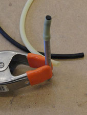
The simplest way to do this is to use the igniter body to extend the secondary charge down into the core itself. Note that the secondary charge isn't contained in the igniter body. Instead, it is loaded in a piece of surgical tubing which is fastened to the end of the igniter with a tie wrap (hence the flare at the end of the igniter).
Using surgical tubing has a couple of advantages for us:
- The size of the secondary charge is adjustable for different motor sizes. (The rule of thumb for thermite is 1g per 1000Ns.)
- The explosion doesn't damage the igniter itself; it just blows apart the surgical tubing.
- The charge is air-tight and tightly contained, which means that it is reliable even at high altitides with low air pressure and oxygen levels.
Thanks to Tony Alcocer for suggesting this idea for high-altitude ejection charges.
Anyone who hasn't yet fallen asleep is now wondering how the glow plug lights the secondary change through the 3" body of the igniter. This was the part that stumped me for a while. I didn't want to use black powder since that would tend to create an explosion and shove the secondary charge down the core and out the nozzle.
What transmits energy nearly instantly without an explosion? Flash paper! For this application, I will use "flash cord" and/or "flash cotton" to pack the bore of the igniter.

Here's the flash cord I'm using, it's just a heavy twine version of flash paper. When packed tightly into a tube, it makes a report much like a firecracker and does quite a nice job of instantly transmitting the energy from the glow plug.
Testing
There were several steps in the design and several refinements along the way that have been glossed over in the text above. For those who want to undetake a similar project, here's what I did to test the system during development.
- EFT and Flash Cord – successful
- Thermite Ignition at Altitude – successful
- Secondary Charge Pattern – in progress
- Real Motor Burn – in progress
Test 1: EFT and Flash Cord
The first test is the most basic: will the EFC & glow plug light the flash cord? Before I had the igniter made, I took a short piece of aluminum tubing and tapped a ¼-32 hole in one end for the glow plug.

Here you can see the components for the test. The EFC has been removed from its ejection charge well and mounted on a board. The silver cylinder to the left of the terminal block is the G-switch; we short it to simulate motor thrust.
This video shows one of the initial tests of flash cord ignition and timing. Note the four flashes of the LED after the battery is inserted, this indicates the programmed delay time (4s). No extra delay has been introduced so we can use the EFC naturally (by using the ejection charge delay time as the staging delay time).
Test 2: Thermite Ignition at Altitude
The second test was to ensure that the flash cord would ignite thermite. I also decided to perform it at low pressure by putting the mechanism into a vacuum bag. This made things more tricky because the whole ignition mechanism also had to be in the bag.
 |
 |
 |
 |
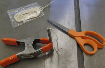
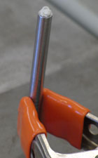
The pictures above show preparation of the igniter:
- packing the flash cord
- flash cord filled to the top
- pouring thermite into the tubing
- capping the tubing
- tubing sealed with zip ties
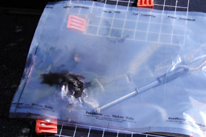
Below we see the components going into the vacuum bag (the trusty FoodSaver®). Note that the project box holds the battery and circuitry, which will be triggered using a reed switch and an external magnet.
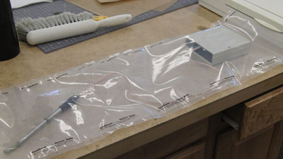
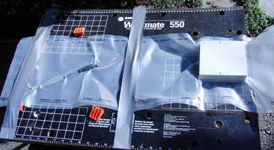
Above is the evacuated bag attached to a bench outside. Note that this is only 1g thermite charge, but I still decided to do it outdoors, which was a good idea.
Here's the video, although not much of interest. You can see the shadow of my hand as I place the magnet next to the box, triggering the reed switch inside.
 |
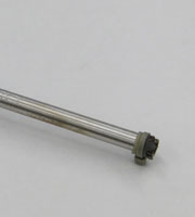 |
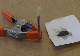
And finally the results after the pop. On the left, above, you can see the igniter (undamaged) and bag (very damaged). On the right is a closeup of the igniter tip.
Test 3: Secondary Charge Pattern
The whole point of placing the secondary charge into the motor core was to get a better explosion pattern to ignite the grain. I wanted to make sure this would happen, rather than having the charge blow down the core and out the nozzle.
Test 4: Real Motor Burn
And finally, the true test: igniting an actual motor. This would of course test the igniter, but also test the seals and how the modified closure fares. In order to save money, I chose a 1-grain 98mm motor, the AeroTech K458. This is a White Lightning motor, like the obvious sustainer motor the AeroTech M750.