GPS Tracking
GPS tracking has been rare in the past, but recently there have been more offerings, lowering prices and increasing functionality. This page goes over the background of GPS tracking and provides lists of what's required to get started.
I'll talk about three systems I'm familar with: the Beeline Big Red Bee, the Real Flight GPS-1 and the Altus Metrum TeleGPS/TeleMetrum. See the References section at the bottom for links to background information and additional systems.
Ken Biba and Grant Saviers wrote great Technical Background sections with details on GPS, radio theory, relative tracking ranges and antennas.
Things to Consider
To help figure out what's most important in choosing a system, ask yourself:
- Am I willing to get a HAM license?
- Do I want a computer or a handheld base station (or both)?
- Do I want an integrated flight computer (telemetry)?
- What range do I actually need?
If figuring this all out seems too complex, you can skip down to my Selection Flowchart.
HAM License
To use the 440MHz (70cm) bands, a HAM radio license is required. Only the simplest, Technician class, is needed (no Morse Code), but it's still an investment of time. I got mine a while ago and suggest that it's worth doing because it opens up more options (even if you never plan to use a HAM radio to chat).
See the ARRL page for the background and requirements. Basically, you take a short written exam that you can study for online.
The Big Red Bee 70cm and all TeleMetrum units transmit on the 440MHz band and require a license. The Real Flight transmits on 900Mhz and does not, nor does the B.R.B. 900. For extreme altitude flights, Beeline makes two units that transmit at 145MHz (2m) and also require a license.
Without a HAM license, you will be limited to the 900MHz band, which has the shortest range. For more information on frequency and relative range, see Ken Biba's section Relative Tracking Range section at the bottom.
Transmitters
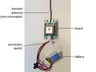
The GPS unit itself flies in your rocket and transmits position to the ground. It has three basic pieces: the electronics board, a transmitter antenna and a battery. On the GPS-1, the GPS antenna is separate. On the Big Red Bee, the battery is integrated.
![]()
Above are the three transmitters considered here. From left to right: TeleGPS, (older) Big Red Bee and GPS-1.
The transmitter needs to be integrated into your rocket, either in the avionics bay or in a separate bay. In order for the transmitter to broadcast to the ground station, the airframe must not be made of metallic or partially conductive substances (carbon fiber or aluminum).
The worst antenna location is between and in-line with threaded rod and near flight computers. Long steel rods (>80% of a half-wavelength) will have a significant attenuation affect. The nose is often wasted space in a rocket, so it makes sense to take advantage of it. See my Plastic Nose Mods video with techniques for installing a bay in a plastic nose cone.
Ground Stations
The GPS unit is flying in your rocket and transmitting information. You also need something on the ground to receive that information and present it in a useful way. The transmitter (flying part) is generally turn-key, but the ground station is more complex.
A ground station is fundamentally made up of three pieces: an antenna, a radio receiver, and a display.
The Real Flight Basestation-2 and Beeline 900MHz receiver come with built-in antennas for 900MHz. The Beeline 70cm and Altus Metrum units require a user-supplied antenna for 440MHz.
For the Big Red Bee 70cm, you need to supply a receiver, which can be a cheap HAM handheld with an external APRS TNC or it can be a more capable radio with a built-in TNC. All other units have receivers available to go with the transmitters.
Another option is to connect the receiver to a computer. This is the route that the Real Flight Basestation-1 and Altus Metrum units take, with base stations that receive the signals and connect to a computer. You don't need a handheld radio to use them in this mode, but you do need a computer out at the launch site.
The Altus Metrum receivers support computers (Windows, Mac OS or Linux) as well as Android phones/tablets for the display. Thus, all three manufacturers have a hand-held solution that you can take with you when retreiving the rocket.
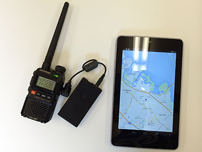
Above is a low-cost solution for 70cm APRS (Beeline and AltusMetrum) using a Baofeng UV-3R receiver and a separate Moblinkd TNC that communicates to an Android device via Bluetooth.
Integrated Telemetry
Once you have a radio on your rocket transmitting position information, the next obvious step is to transmit information about the other on-board systems such as the flight computer.
Most of the systems discussed are only positional, but the Altus Metrum TeleMetrum transmits its state as well as position in the same stream. This means you can monitor the flight computer status when you're back at the flight line and during the flight.
Beeline
The Big Red Bee has been around a while and was the first GPS system I used.
- Low-priced
- Good range with the highest-powered transmitter
- 70cm requires a radio with APRS support
- 70cm requires a HAM license, 900MHz does not
Transmitter
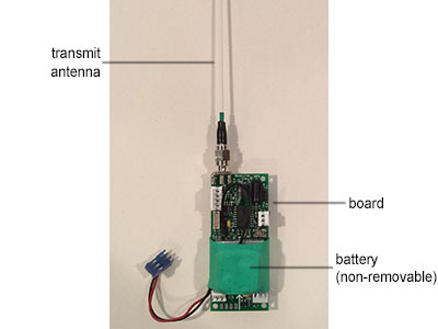
The (older) Big Red Bee 70cm weighs 0.12# (55g) and fits into a 38mm tube. The battery is mounted to the board and charged through a jack, which doubles as the switch. Note that this photo is of my (older) unit; newer units vary slightly in apperance.
A higher-power version of the 70cm unit exists, which provides extra range. Beeline also offers a transmitter that broadcasts on the 145MHz (2m) band, which has even longer range than 440MHz (and much longer than 900MHz). The 2m units are the standard for ultra-high rocket and balloon flights.
Ground Station
The Big Red Bee 70cm requires the user to supply a HAM radio and a way to decode APRS packets. One way is higher-end HAM radio with the APRS TNC built-in. Another option is to use a cheap Baofeng radio and decode APRS on a computer, phone or tablet. The former is simpler, but the latter provides better a display with maps.
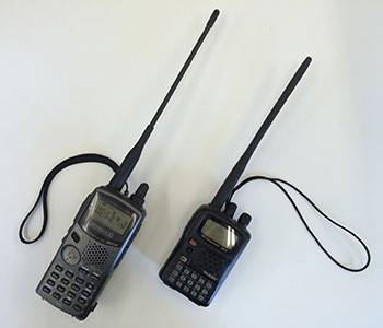
Above are two typical H/T (hand-held transcievers) that have built-in APRS TNCs from Kenwood and Yaesu.
The Big Red Bee 900 has a matching ground station that displays coordinates on a small LCD panel.
Real Flight Systems
The Real Flight Systems GPS-1 is a nicely integrated system, with everything included.
- No HAM license needed
- Nothing additional required
- Most expensive
Transmitter
The GPS-1 transmitter is the largest by far, but has the most options for arranging the components. The GPS and transmitter antennas are both removable and the battery is also separate. The whole thing weighs 0.64# (276g) and the board fits into a 54mm tube.
Note that Real Flight Systems also makes the GPS-2, which incorporates pyro outputs that can be fired from the ground, via 2-way telemetry.
Ground Station
Real Flight Systems provides the complete ground station (including antenna), called the Basestation-2. This is a hand-held unit that allows tracking without a computer. These systems use a proprietary protocol, so the transmitters may only be used with their receivers.
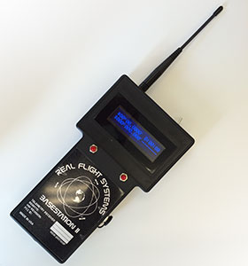
The Basestation-1 is a stand-alone unit as well as featuring NMEA construction. One can also use a MAC/Windows/Linux computer serial console to take advantage of the additional telemetry and remote control features of the GPS-2.
Another nice feature of the GPS-1 and GPS-2 is the entire NMEA raw output of the uBlox chip can be opened in Google earth (GPS log file) by simply removing the Micro-SD card and inserting into a PC.
Altus Metrum
Altus Metrum is the newest arrival and has disrupted the market by integrating GPS into flight computers (on board).
- Low-priced (TeleGPS)
- Medium-priced with flight computer (TeleMetrum)
- Requires a computer or Android phone/tablet
- Requires a HAM license
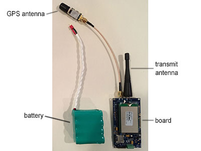
Transmitter
The TeleGPS is the smallest of these trackers. It fits into a 29mm tube and weighs only 0.04# (18.4g). It has an external battery, but the antenna is a wire soldered to the board. (The switch on the battery lead is my addition.)
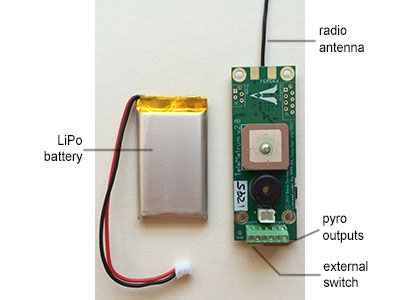
The TeleMetrum includes a flight computer as well. It's the same width and twice as long as the TeleGPS and uses a larger battery. There is also the TeleMega with more pyro channels.
Ground Station
Altus Metrum sell the TeleDongle receiver for connection to a computer (Windows, Mac OS or Linux) via USB and the TeleBT for connection to an Android device via Bluetooth. In both cases, the receiver antenna is user-supplied. These units communicate via a proprietary protocol as well as supporting APRS.
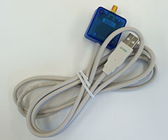
Above is a photo of the TeleDongle receiver for use with a computer via USB. The user must supply an antenna for 440MHz, such as the Arrow 3-element Yagi.
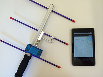
Another option, shown above, is to use the Bluetooth-enabled TeleBT with an Android device. This is probably the most convenient as you get maps without needing to bring a laptop.
Product Comparison
In this table, "TX" (transmitter) refers to all the parts that fly in the rocket and "RX" (receiver) refers to all the parts of the ground station. Prices taken from manufacturer websites on July 9, 2014; a 440MHz antenna estimated at $50 (Arrow 3-element Yagi).
| Beeline | Real Flight | Altus Metrum | ||||
|---|---|---|---|---|---|---|
| BRB 70cm | BRB 900 | GPS-1 | GPS-2 | TeleGPS | TeleMetrum | |
| TX weight | 55g | 276g | 18g | 36g | ||
| fits tube | 38mm | 38mm | 54mm | 54mm | 29mm | 29mm¹ |
| frequency | 440MHz | 900MHz | 900MHz | 900MHz | 440MHz | 440MHz |
| HAM license | required | none | none | none | required | required |
| bi-directional | no | no | yes | yes | no | yes |
| antenna | removable | removable | removable | removable | fixed | fixed |
| battery | on-board | on-board | separate | separate | separate | separate |
| pyro channels | no | no | no | yes | no | yes |
| flight computer | no | no | no | no | no | yes |
| TX price | $215–260 | $200 | $300 | $500 | $200 | $300 |
| RX antenna | with radio | available | included | included | user-supplied | user-supplied |
| RX radio | user-supplied | available | available | available | available | available |
| computer | no | no | no | optional | required | required |
| system price | n/a² | $330–400 | $550–600 | $350–400³ | $450–500³ | |
| manufacturer | link | link | link | link | link | link |
¹ The board fits, but not the stock battery.
² No base station; requires a user-supplied antenna and radio w/ APRS.
³ User-supplied antenna and computer (Windows, Mac OS, Linux, Android).
Selection Flowchart
Here's a suggested flowchart for the price-conscious who want to get started in GPS tracking and aren't interested in advanced telemetry features or extreme altitude.

These are suggestions based on my estimate of typical sport rocketry needs. I own the BRB 70cm, GPS-1, TeleGPS and TeleMetrum.
If range is the most important consideration, the Beeline 2m units are the standard for ultra-high rocket and balloon flights. I've not owned one of these myself, but I will definitely use one for any future high-altitude (black sky) attempts.
Technical Background
Global Positioning System (GPS)
by Ken Biba
GPS is one of several global positioning systems (generally GNSS: Global Navigation Satellite Systems) based on constellations of satellites broadcasting time and position that can be used to triangulate, based on the speed of light, a position in three space (or in the special case of the surface of the earth). GPS is a constellation of 24 satellites, operated by the United States Department of Defense. Similar constellations are being constructed by Europe (Galileo), Russia (GLONASS) and Chinea (Beidou).
A tracker requires not only a good telemetry link to the ground, but a good GPS receiver on board to determine position.
GPS is based on the fundamental idea that each satellite has a very accurate atomic clock and a very accurate position. Each satellite broadcasts its time and position continuously at a frequency of about 1.5 GHz. A ground station, such as the GPS chipset in a tracking module, receives these time and position messages from the collection of satellites in the constellation above the local horizon that are visible to the ground station's antenna and receiver. From a computation of the position of each satellite, the distance to each satellite based on the speed of light and the time of each satellites broadcast—a ground station can do a trigonometric calculation to determine the location of the ground station. At least three satellite views are necessary for a 2D position on the surface of the Earth and four satellites are required for a three dimensional solution that includes altitude.
GPS can provide a very precise position subject to three constraints: physics, regulatory and chipset implementation.
The physics of radio transmission thru the atmosphere where small differences can dramatically effect the calculated position constitute the bulk of possible errors in GPS position. Such sources of error include:
- Ionosphere effects (± 7 meters)
- Shifts in satellite orbits (± 3m)
- Clock errors in satellite clocks (± 3m)
- Multipath effect (± 1m)
- Tropospheric effects (± 1m)
- Calculation and rounding errors (± 1m)
In practice, these errors result in an estimated 2d position error of 10m 95% of the time and an estimated altitude error of 30m 95% of the time.
GPS has regulatory restrictions. Precision navigation can be used to create intelligent weapons so the US government (and other governments for their own constellations) regulate GPS receivers to mimimize that risk. In the beginning, COCOM (Coordinating Committee for Multerlateral Export Controls) were governmental restrictions placed on technology exports to minimize risk of GPS engines being used in weapons. Now formally disbanded, the remnants of these controls are now appearing in export controls under the ITAR set of rules administered internationally and by the State Department in the United States. The core ITAR restriction regards velocity—placing a maximum reporting velocity of 515 m/s. Special space capable GPS engines can be acquired that can exceed this limit, but have handling restrictions and are quite expensive.
Most commercial GPS chipsets are designed to solve the high volume problem of 2D position for a vehicle or person moving at slow speed on the surface of the Earth. Most GPS chipsets are optimized for this problem and their internal triangulation algorithms can become quite confused when placed in a rocket, moving at high speed, in three dimensions. It is important to use only GPS chipsets that are capable of compensating for high dynamic motion in trackers designed for rockets.
For example, here is a chart plotting the position of a rocket by Ken Biba that flew to about 45k' AGL at Black Rock. It contained a collection of avionics but in particular two GPS trackers—one based on a chipset from Magellan capable of high dynamics and packaged in a tracker by Big Red Bee and the second a very popular chipset designed for surface of the Earth tracking—the SiRFStar IV chipset.
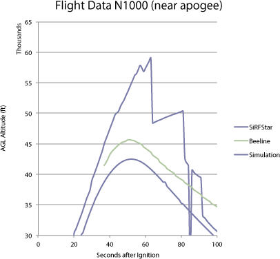
It is easy to see that the SiRFStar chipset became VERY confused and reported altitude and position that were not only wrong, but physically impossible. The Magellan chipset in the BigRedBee performed quite well and with high precision.
Today, the best GPS chipset for rocket tracking comes from uBlox in Switzerland and is the choice of almost all commercially available rocket trackers.
In deference to regulatory requirements, the uBlox chipset does quite well in rockets, particularly uBlox 6 and later versions. The chipset will stop reporting position when velocity exceeds 515 m/s and return to reporting position when velocity drops below 515 m/s. It is rated to 50 km maximum altitude, but the factory reports that it will continue reporting position above that altitude albeit with decreased precision. It is rated to only 4G maximum acceleration while in operation, but it does rather well up to about 8G in practice.
Digital Radio Communication
by Ken Biba
This is an introduction to some key radio terms that help you understand digital radio communications a bit better. The core concepts try to identify how much data can be communicated at what range. We determine this through the procedure of the link budget. The link budget breaks down a complex radio link into roughly seven basic elements. Changes in one or more of these determine the effective range at a specified level of performance.
Modern radio telemetry can take place in a number of frequency bands that the Federal Communications Commission has allocated for this purpose. Using products in some of these frequency bands are open to all users without a special license, operation in other bands require a basic HAM radio license. There are three frequency bands that are commonly used for tracking. The 145 MHz band (commonly called the 2m band after its wavelength) is a HAM only licensed band. It is only 4 MHz wide from 144–148 MHz and is widely used for narrow band tracking using the HAM standard APRS protocol. It has substantially longer range than higher frequency bands and is the de facto standard for stratospheric balloon tracking with ranges of 100s of miles. The second band in use is the 70cm at 420–450 MHz—though commonly used for tracking at about 435 MHz. It is also a HAM only band (though there is a narrow unlicensed band at low power available). It has about a third of the range of the 2m meter band. The third band is the 33 cm band at 900–920 MHz. This is an unlicensed band for individuals (though vendors must type certify radios) and is used for many applications—WiFi, baby monitors, industrial meat cookers and HAMs. With 20 MHz of bandwidth, it is possible to build radios that have more bandwidth and can serve applications other than slow, narrow band ones. It has about half the range of the 70cm band.
The basic telemetry of position is not a high bandwidth endeavor. A quite low speed data link of less than 1 kilobit/second can keep up with the essential data of latitude, longitude and altitude. Transmission of additional data (temperature, battery voltages, payload data, airframe attitude) telemetry is optional and may require extra bandwidth. Compression on the link can help. Inefficient encoding of this information will require addition speed on the link and this additional speed comes at the price of reduced range.
We conventionally measure link budget in units of decibels—a base 10 logarithmic unit that measures the ratio of two values. A 3 dB increase (or decrease) in any of the basic components of the link budget represents a doubling of the overall link budget (and of that component) but only an increase of about 1.4x in range due to square law propagation of radio waves. In order to double range, an increase of 6 dB in the link budget—in any of the components or collectively from all of them—is required.
Link budget is (approximately) composed of transmitter power, transmitter antenna gain, path loss due to distance, receiver antenna gain, receiver sensitivity, data modulation rate and coding. There are a bunch of other, usually more minor issues, like noise, losses due polarization, connectors, length of wire to/from antennas, etc. I am going to avoid those for the moment and concentrate on the big seven above. Link budget is measured in units of decibels (dB). A change of 6 dB in the link budget—whether through power, antennas or receiver sensitivity—roughly doubles the range of the radio link.
Transmitter power: Since we are talking about small payloads that take propellant to loft, weight and size matter. To get the doubling of range solely by increasing transmitter power, that 6 dB increase means increasing transmitter power by a factor of 4. And since generally, the transmitter is the most power hungry element of a tracker, that means increasing battery capacity (and weight) by a factor 4. For high transmitter power trackers, the battery is often much larger and heavier than the tracker.
Transmitter antenna: Antenna gain is a measurement of the additional advantage that comes from focussing the radio waves from a transmitter in a particular direction, or of a receiver in a particular direction—much like a human being might cup a hand behind an ear to better hear a particular conversation across a crowded room. Transmitter antennas, because we generally have little control over the attitude of the airframe, are usually omnidirectional and have little to no gain to add to the link budget. Indeed, some small antennas have negative gain. Most amateur rocketry antennas are simple, low gain dipoles with an omnidirectional pattern. We can assume that the attitude of the antenna will be unknown.
Most trackers put simple antennas on the package on the rocket and more complex, and higher gain, antennas on the ground station.
Path Loss: Radio waves propagating in free space lose energy over distance. This loss increases with distance and with frequency—and is a key element of determining range. Radio and antenna engineers use the following simplified formula (also known as the Friis transmission equation) for an estimate of the path loss between two simple antennas in free space. The path loss in dB is:
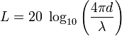
where L is loss in decibels, λ is the wavelength and is the transmitter–receiver distance in the same units as the wavelength.
If we do this equation for the three most interesting frequency bands for trackers (2m, 70cm and 33cm or by frequency 145 MHz, 435 MHz and 910 MHz) we find that the 435 MHz band only has about a third of range of the 145 MHz band (with a 9.1 dB additional path loss due to frequency) and the 900 MHz band has about half the range of the 430 MHz band (with an additional 6.5 dB path loss due to frequency).
Receiver Antenna: Receiver antennas are an integral part of the ground station and are one the most important parts of the system. The proper choice can dramatically change the range and utility of system. Antennas come in many flavors and are one of the most complex and arcane technical areas of radio design. But we can think of them in three broad categories: an entry dipole antenna, much like on standard handheld radios, a directional antenna, like a Yagi, that gives substantially higher gain but must be pointed at the transmitter and more complex antennas designed for LEO satellite communications for much longer range.
A simple dipole antenna may have 0–3 dB of gain an is often designed for an handheld radio held verticall, and is optimized to listen in a doughnut shaped patterns, leaving gaps towards the place where most rockets are: towards the zenith. For rockets flying not very high, say under 30k' AGL, these antennas will likely be adequate. These antennas typically cost $10–20.
A Yagi antenna is the most common ground station gain antenna available at both the 2m and 70cm bands. A simple 3 element Yagi can deliver 6 dB of gain when pointed at the rocket and thus often double the range of the tracker over a simple dipole. Increasing the Yagi to 7 elements can further increase to 12 dB of gain and a further doubling of range. The increased gain and range of these 7 element yagi's do have a price: a narrower field of view that requires more precise handheld tracking. These antennas cost from $50–100.
The most complex in design, yet often simplest to use ground station antennas, are designed for communications to LEO satellites in the 2m and 70cm bands. These antennas use a sophisticated quadrifilar helix design that is small, compact, omnidirectional and circularly poarized to minimize polarization losses due to tumbling payloads. Because they are omnidirectional, yet high gain from the internal pre-amplifier, they do not require manual tracking to follow the payload yet give extraordinary range. They can cost up to $200 (satellite antenna w/ LNA), but can increase range over a simple dipole by a factor of 8.
Receiver Sensitivity: Another key item is the lowest signal level that a receiver can successfully receive and decode as meaningful information. This is one of the major areas of smart modem development since modern digital receivers have made dramatic strides in recovering lower power signals and improving noise resistance. Modern telemetry receivers can decode signals down to −110 dBm when there is little to no external noise. Most trackers are using modern digital receivers and get surprisingly similar performance.
There is external noise for all radios But it is different among the three bands in two important ways. The 144 and 430 MHz bands are largely licensed HAM bands and only HAMs, trained to use minimal transmitter power, are allowed to the use the bands. This generally results in much lower noise than the 900 MHz band that is publicly accessible with individually unlicensed radios. Range for trackers in the 900 MHz bands will likely be degraded less by noise in remote, rural areas than in urban areas where 900 MHz noise can be be quite loud. To a lesser extent, this will also be true even for the licensed bands of 144 and 435 MHz.
Data Modulation Rate: There is a 3 dB change in link budget for each factor of 2 change in data modulation rate—representing the change in energy per bit transmitted. For example, changing the data rate from 1200 to 2400, is a 3 dB decrease in link budget and a change from 1200 to 38400 baud is a 15 dB change in link budget. A 3 dB decrease in link budget will occur with a doubling of modulation rate and a 3 dB increase in link budget will occur with a halving of modulation rate. The greatest range is attained with the lowest possible modulation rates. Almost all current trackers use a variation of a very simple, though robust, modulation scheme termed Frequency Shift Keying, that is quite robust and designed for narrow band communications.
Coding: Another opportunity of modern smart digital modems is to apply advanced communications coding methods to the link. These codes, pioneered for GEO satellite communications and for communications to deep space satellites, allow for enhanced range by the use of redundancy coding to allow recovery of very faint signals. These techniques can add another 3–6 dB to the link budget and perhaps double range and increase robustness of the link in the presence of obstructions. Altus Metrum has pioneered including these methods in its products.
Relative Tracking Range
by Ken Biba
I am uncomfortable with predicting actual range, but the above basics allow us to compare relative range, assuming the same ground station antennas. If we use the current 100 mW Beeline as a baseline reference (it uses the simplest protocol APRS), we get a comparison table like this:
| System | Relative Range | Relative Link Budget (dB) | Wavelength (cm) | Frequency (MHz) | Power (mW) | Modulaton Rate (kbps) |
|---|---|---|---|---|---|---|
| BeelineGPS 70cm HP | 100% | 0.0 | 69 | 435 | 100 | 1.2 |
| BeelineGPS 70cm | 40% | −8.0 | 69 | 435 | 16 | 1.2 |
| BRB900 | 26% | −11.6 | 33 | 910 | 250 | 10 |
| BeelineGPS 2m HP | 2140% | 26.5 | 207 | 145 | 5000 | 1.2 |
| BeelineGPS 2m | 955% | 19.5 | 207 | 145 | 1000 | 1.2 |
| Real Flight GPS | 27% | −11.5 | 33 | 910 | 1000 | 38.4 |
| TeleGPS | 40% | −8.0 | 69 | 435 | 16 | 1.2 |
| TeleMetrum | 63% | −4.0 | 69 | 435 | 40 | 1.2 |
| TeleMega | 63% | −4.0 | 69 | 435 | 40 | 1.2 |
| RDAS (430 MHz) | 50% | −6.0 | 69 | 435 | 50 | 2.4 |
| RDAS (900 MHz) | 24% | −12.4 | 33 | 910 | 50 | 2.4 |
Antenna Basics
An analogy
Antennas radiate electromagnetic waves, something we can’t see, but since we can see light and generally experience how it is focused (or not) I will use light as an analogy to help understand how antennas work. There will also be a number of references to amateur radio antennas, since that is one of my areas of interest and experience.
Imagine a small bare light bulb on the end of a small diameter stick, it will approximately radiate light equally in all directions. If we measured the light falling on the inside of a sphere with its center at the filament, the intensity of the light would be the same everywhere. This is called an isotropic source, important as a reference for measuring antennas for rockets since in flight they are practically radio sources in free space.
For radio waves there are no real isotropic sources, so any antenna we happen to use changes the intensity of the radio waves hitting the inside of that imaginary sphere in azimuth and elevation. Some antennas act as flashlights, concentrating the waves in a conical pattern (yagi-uda), others make figure 8 patterns (dipoles), and some donut like patterns (verticals near real ground). By selecting and properly deploying the right antennas at both ends we can make better or worse the signal level at the APRS receiver. One principle to remember is that antennas have reciprocity—they pattern they produce in transmitting is identical to the one they have in receiving.
How we measure the antenna pattern
For free space measurements, the gain of an isotropic source is the best “zero” reference, and is measured in decibels referred to isotropic, abbreviated dbi. Decibels are a logarithmic measure, 3dbi is twice the power, 6dbi 4 times, and 12dbi 16 times (2x2x2x2). The old adage in ham radio is spend money on antennas before spending money on amplifiers, it is much better “bang for the buck”. A few hundred dollars of antenna can outperform thousands spent on an amplifier.
While our rocket is lazing about in free space, our ground station is not. So, antenna patterns get a bit more complicated when the radio waves interact with mother earth, conductive objects, and the ionized layers of the atmosphere. We don’t fly high enough to worry about the latter. For conductive stuff, the effect is significant from metal objects, sea water, the human body at VHF/UHF, playa alkali, and even dry dirt.
This discussion is 70cm (430 MHz) radio link and APRS centric. You will see various not 430 MHz antenna frequency and elevation notations on some of the printouts, ignore them since they are taken from antennas for other frequencies already modeled and then moved the right number of wavelengths above ground etc. That is another principle of antennas—for the most part they scale easily in frequency.
What we want/need for antennas
Since our flight transmitter when descending may have time varying odd orientations with respect to ground, ideally we would like an isotropic source, but can’t have one. So, we make do with the whip antenna, hopefully one that is a quarter wavelength (wl) long since that matches the output of the transmitter well and also coaxial cables. However, a ¼ wl whip is only half an antenna, actually half of a dipole, so it needs “something” to use as the other half. The “something” could be the coax feed line, or ¼ wl radials as in a ground plane antenna, or the printed circuit board of a BigRedBee or an aluminum bulkhead the whip is mounted to. What that “something” is, does have an effect on the pattern and the peak dbi gain.
Antenna performance prediction is a “rocket science”, fortunately well understood and available cheaply (some free) in variants of the National Electromagnetic Code developed on mainframes a long time ago. A not free version is EZNEC ($90 and up, free demo) which is very common, and 4NEC2 is available free. Both are fairly easy to learn and use for simple antennas. Analogous to RockSim. Experience and range testing have proven the accuracy of this software. One doesn’t need to know Maxwell’s equations to get useful results.
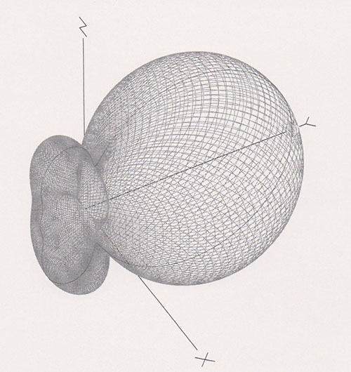
Here is what EZNEC produces as outputs for a ground plane vertical in free space: The antenna looks like this, with the vertical part along the axis of the rocket. EZNEC shows the RF current in each element, which are the curved lines.
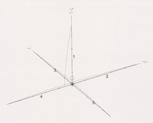
The 3D pattern is, again the vertical ¼ wl whip is the Z axis.
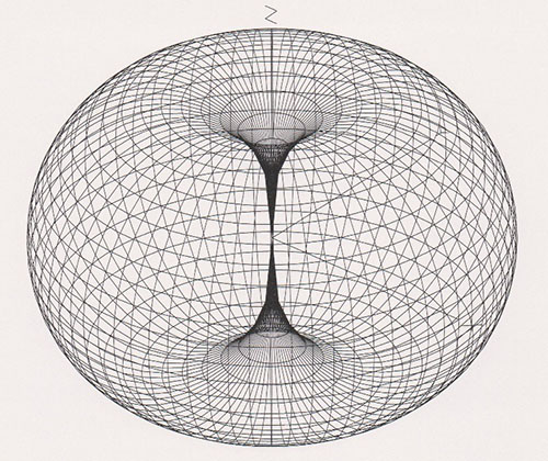
If we take a slice of the torus, it looks like this and we now can measure the dbi gain, the outer ring is +1.46 dbi, which is the peak gain of the antenna. The poorest gain, along the axis of the rocket, is worse than −30 dbi, in theory even more.
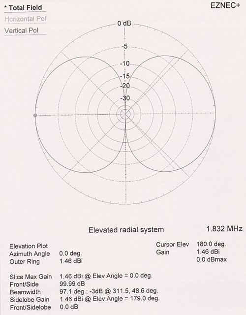
There is both good and bad news in this pattern. The good news is the antenna is omni-directional in the horizontal plane, so whatever the spin of the rocket transmitter, the signal will be the same. Other good news is that for some amount of pitch or yaw, the signal doesn’t drop off dramatically. The −3 dbi from peak level is a common reference in antenna modeling and the program conveniently drew lines marking that at about ±40 degrees to the rocket axis. The bad news is when the rocket is high and directly overhead, the gain of the antenna is very low, −30 dbi or more. It is as if we turned the power output of the transmitter down by greater than a factor of 1000! If the rocket arced over and is not overhead, then things aren’t as bad.
Now let’s look at the ground station end, where we chose to use the same ground plane vertical. An HT with a rubber ducky is a poor version of that, with overall probably −6 db less gain than a full size antenna at 70cm. Now the earth interacts with the antenna about 6’ high in our hand (2.5 wavelengths up):
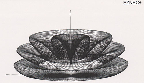
Yikes! It looks like the Mad Hatter gone crazy. Now ground reflections are adding to and nulling the signal at some elevations. Again, we see that along the axis of the vertical part the gain is extremely low, not good when the rocket is overhead. In azimuth the software predicts it is uniform, but that is unlikely since our body is interacting with the antenna. Experience shows that holding an HT in the direction of the source is better than source behind us. That effect is very difficult to model, except with the best analysis software ($k’s).
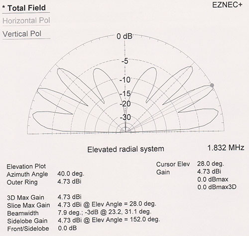
Now we can see why the APRS packets might come and go on descent. Some pitch and yaw of rocket axis when in a receive antenna null and the total gain loss could be 45 db. Another “bad news” is when the rocket is close to earth, less than 5 degrees above the horizon. The receive antenna has very low gain, even though the transmit one is now near maximum gain. So we want to remember the data from the last few good packets. Other bad news is that we can’t put ¼ wl radials into most rocket bodies, so something else is acting as the other half of the dipole for the whip. Generally that means less peak gain, and then we ask the whip to transmit in proximity to other stuff and through a painted fiberglass body which would attenuate the signal and distort the pattern. Transmitting through carbon fiber is a really bad idea. It would be cool to have some measured attenuations.
Doing better
There are fancy surface antennas or slot antennas which can avoid some of the transmit side problems, but they are beyond the scope of this introduction. So we generally “make do” with whips inside the rocket body. The more conductive surface area the whip is grounded to, generally the better for the pattern and gain. An aluminum bulkhead with thru SMA connector to mount the whip is a very good alternative. It also keeps the RF away from the avionics. Note that the 2m high power transmitters would need a 0.5m long whip to be ¼ wl, which is usually impossible. So, various compromise shortened antennas (rubber ducky) are used, but they might be down 6 to 10 db in peak gain reducing the effective transmitter power by 4 to 10x. There’s no free lunch here.
What can be substantially improved is the receive side. Let’s move the 70cm receive ground plane to 14’ high:
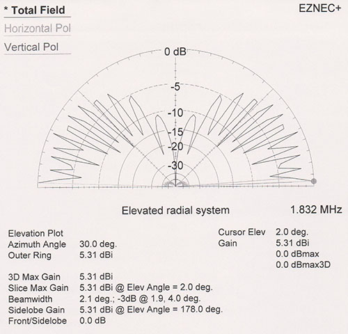
Now the peak gain is +5.3dbi and at a very low angle. Since we could be on a Harbor Freight 16’ telescoping flagpole, the local human and RV interaction is negligible. While there are still deep nulls, they are smaller and more frequent in elevation angle. An eyeball integration of this pattern vs the HT at 6’ shows more average gain at lower elevation angles. Thus, raising the ground plane to 14’ high would make a better first half of ascent/second half of descent omni-directional antenna. Something essential to have if we weren’t certain where to point a yagi.
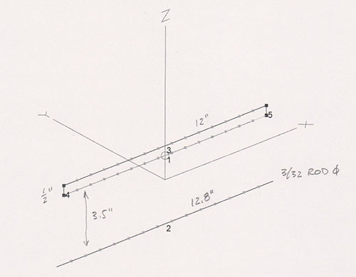
Another need is more gain for when the rocket is high and near overhead. A yagi pointed up if the beam width isn’t to narrow would work, we will investigate yagi patterns further on. Another simple choice is what amateur radio calls a NVIS antenna—Near Vertical Incidence Skywave, the pattern is straight up when a dipole is about 0.2 wl above ground. For 70 cm precisely where real RF ground is relative to what we are standing on is tricky, so it is better to make a fake ground up in the air. Here is one I modeled—a folded dipole with single reflector element at 6’ above ground, easy to make from brass or copper brazing rod. Or, if you prefer call it a 2 element yagi. By being at 6’ above the playa we avoid pattern distortions that real earth would cause. The pattern is straight up and nearly uniform in azimuth. Note the pattern is height sensitive so stay around 6’ up.
The antenna design using 3/32 brazing rod, 50 ohm feed to a folded dipole:
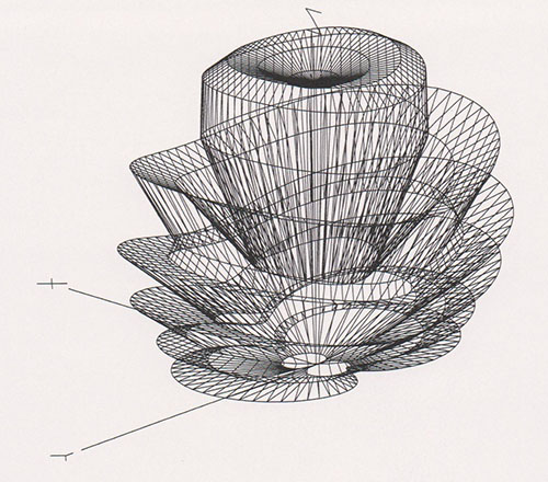
The 3D pattern of the 435 MHz NVIS at 6’ elevation:
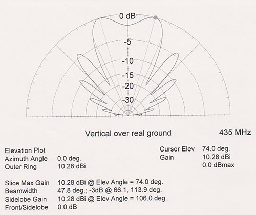
A slice of the NVIS pattern showing 10.3 dbi gain, and is very symmetric around Z axis:
We don’t need a circularly polarized antenna such as those used for LEO satellites. In fact there are some reasons to not use them to receive a linearly polarized signal. But they do work, are hard to make for 70cm, or commercially cost $$.
So you might ask at this point, why can’t I have an antenna with gain everywhere? Let’s go back to the light bulb example. I can focus a 5 watt bulb in various ways, but total optical power output doesn’t change. I can use a bigger power source, and that changes the total radiated power but not where it is pointed. Antennas work the same way. Technically, the integration of intensity over the inside of our imaginary sphere always sums to the same power, regardless of the way the antenna focuses the energy.
Yagis as receive antennas
At 70cm, a fairly large Yagi is easy to hand point, but we need to know where to point. The more elements, the more the beam becomes like a focused spotlight. Here is the pattern for a 5 element yagi on a 2 foot long boom in free space, perhaps when hand held and pointing at 45 degrees elevation.
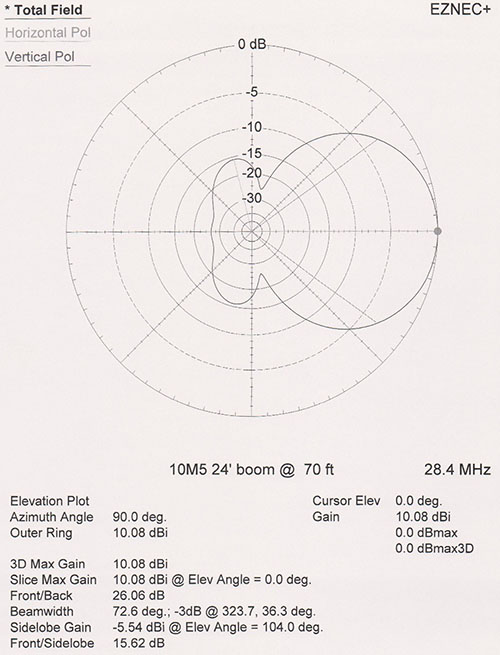
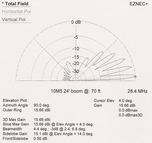
Note the peak gain is 10 dbi and the 3 db beam-width is ± 35 degrees, so there is a decent chance of capturing the signal if another source has determined azimuth and elevation. There is also a lot of sky with nada gain. When the yagi boom is horizontal with only azimuth pointing peak gain is 15.7 dbi due to earth reflections. This is a 10 db improvement over the elevated ground plane previously described for when the transmitter is low in the sky, about 4 degrees above the horizon. However, with this yagi 6’ above ground on 70cm, it develops deeply lobed gain in elevation, so while we have great gain on the peaks of these lobes, the gain degrades a lot in between. The main lobe −3 db beam width is about 4 degrees high by ± 27 degrees wide, quite a challenge if a person is aiming the antenna.
Other ways to improve the radio link
First is to not lose signal. Coaxial cables have well characterized db loss per 100’ vs frequency curves. Radio Shack RG58 is not a good choice at most any frequency, let alone VHF/UHF. Foil+braid or foil+foil shields over foam dielectric cables are a must. Here are some lengths for 2 db of loss at 430 MHz:
| RG58 | 16 ft |
| RG8X-Low loss (braid+foil) | 30 ft |
| Belden 9913F7, Buryflex, LMR400 | 80 ft |
| LDF4-50A heliax | 250 ft |
My favorite is Buryflex from DavisRF for durability and ease of attaching connectors. Speaking of connectors, at 430 MHz we are at the crossover between the popular UHF style (PL 259/SO-239) and ones designed for higher frequencies such as N, SMA, and DIN connectors. Any of these will work ok in the applications being discussed.
More electronics horsepower at either end can help. Higher power transmitters and low noise preamplifiers can improve the radio link. Low environmental noise at high power launch sites permits the use of low noise amplifiers ahead of the radio for more receive gain. Even high grade (Yaesu, ICOM, Kenwood) HT’s can benefit at 430 MHz.
For most, the modem that demodulates the AFSK (Audio Frequency Shift Keying) radio signal is a black box somewhere inside the APRS TNC or PC software stack. This modem turns the receiver audio output into the 1’s and 0’s of APRS packets. Some reports indicate they vary significantly in performance (bit error rates vs signal to noise) and with significant sensitivity to which radio is connected. This is another area where the signal chain can be improved. Plus, perhaps the AFSK modulation side of the APRS transmitter in the rocket. Now we are diving into the deep end of the pool, so let’s stop here, but not before outlining the “dream APRS ground station”.
Dream APRS ground station design
We have one really great weapon—the fact that APRS packets have error detection. Thus we know good packets from bad ones and can have multiple receive only links and only use the good ones. An APRS AFSK modem (demodulation side) that uses this principle was described in ARRL QEX July/August 2012. The idea can be extended to multiple receivers and antennas.
Starting with antennas, we have:
- A 14’ elevated ground plane for on the pad, 1st half ascent, and 2nd half descent
- A NVIS 2 element at 6’ for high overhead and apogee
- A 5 element yagi ready if we have too much wind drift
Assuming:
- Each antenna is connected to its own HT, Baofengs for $40 each aren’t so bad, could add preamps.
- Each HT connects via its own USB sound card to decent PC, e.g. i5 quad core.
- Use the 4X6IZ software modem for each sound card to an APRS stack for each antenna.
- Just a small matter of software and some cables!
Digging deeper into antennas & APRS links
- ARRL Antenna Book, includes CD with freeware
- Antennas, Kraus (the classic, deep)
- Data Transmission, Bennett & Davey, 1965 Bell Labs (theory of AFSK modems)
- ARRL, many QST and QEX antenna and APRS articles arrl.org
- A High-Performance Sound Card Modem, Sivan Toledo, 4X6IZ, QEX July/August 2012
- EZNEC.com
- www.qsl.net/4nec2/
Beware—there is a lot of mythology and bunk regarding antennas. Marketing db’s are plentiful. Some amateurs claim greatness for the particular antenna they have and then EZNEC demonstrates it worse than a plain old dipole.
References
- Altus Metrum
- Big Red Bee
- Real Flight Systems
- ARRL Technician License
- Standard position reporting (APRS)
- Global Positition System (GPS)
Other GPS trackers with which I am not familiar: