Delta II
Originally, the Delta II project was conceived as a spectacle for the first XPRS launch in 2002. However, it turnd out that I was unable to attend XPRS that year (I got married instead) and the project didn't get beyond the planning stage until mid-2003 when I picked it up again.
I've been interested in parallel staging and the Delta IIs make great rockets to model with their nine drop-away boosters. There are lots of interesting problems that needed solutions and work development and building began in late 2003. It still will be a spectacle rocket and may well fly at an XPRS in the near future.
In 2016 we moved and all projects that had been sitting for more than five years without progress were abandoned. This one one of them.
The Pictures
The Design
Dave Flynn, another member of ROC, and I have discussed the project. He has been working on a Delta II as well, using his custom-made booster droppers.
Erik te Groen sent me a high-resolution image of the NASA swoosh logo and I was able to use his paper model images to draw the Delta triangle logo. David Shultz pointed me to the NASA Pathfinder site which has some great images. (In particular, KSC-96EC-1321.jpg has a clear photo of all three logos.) I was able to use use that to draw the JPL Mars Pathfinder logo. Steve Gerber sent me an image of the decals he used on his Delta II along with the information that the triangle on the rear of the rocket is different than the one one on the front. I made the slight modifications to the mission 240 triangle, completing the set.
 |
 |
 |
||
| drawing (PDF) | drawing (PDF) | |||
 |
 |
|||
| drawing (PDF) | image (GIF) | |||
(I drew the McDonnell Douglas logo, but that was so easy, it's hardly worth mentioning.)
As always, most the information on the rocket comes from Rockets of the World (Third Edition, page 238). Thanks again to Peter Always for this amazing work!
Overall Design
THE first thing to do is pick the scale. Since this rocket is mostly cylindrical, I decided to stick to standard tubing sizes. Starting with the booster, I tried different tubing sizes to see what fell out. (Overall length is without the nozzles.)
| Scale | Booster O.D. | Main O.D. | Payload O.D. | Body Length |
|---|---|---|---|---|
| 100% | 40.1" | 96.0" | 114.0" | 1502.8" (125') |
| 6% | 2.4" | 5.8" | 6.8" | 90.2" (7.5') |
| 8% | 3.2" | 7.7" | 9.1" | 120.2" (10.0') |
| 10% | 4.0" | 9.6" | 11.4" | 150.2" (12.5') |
Note that the 8% scale has a pretty good hit rate: the boosters are widely available 3.0" tubing (3.1" O.D.) and the main body is 7.5" tubing (7.65" O.D.) available from Loc/Precision and Giant Leap. The payload section is not a standard size, but can be molded or turned since it is a special shape. Also, 10½ feet tall (including the nozzle) is a manageable overall size.
The next simplifying assumption was the elimination of the second and third stages. (The prototype had 3 stages of the central rocket.) My version will use that space for staging electronics and the recovery system.
Now, what motor mount combinations fit in a 7.512" diameter tube? A little experimentation showed that three 76mm (3.1" O.D.) tubes fit comfortably. However, I decided to install a single 98mm motor mount tube (MMT) since this allows me to accomodate the AeroTech N2000. The N2000 burns for 6.8 seconds, which allows a nice arrangement with J350s (1.8s burn time) in the boosters. (In the prototype, 6 of the 9 boosters were lit with the main engine and the remaining three were lit after burnout of the first set of boosters.)
The key aspect to this rocket is the drop-away boosters. The boosters need to be attached in a way that transfers the force of the J350s to the airframe securely and then be able to drop away. Juerg Thuring built a nice drop-away mechanism for the Arianne project and I liked the way he did the clips. He uses R/C servos and I wanted to use "explosive bolts," but the clips which transfer the thrust are similar.
Now that the basic parameters were defined, I proceeded to the detailed design. Here are the drawings done for this rocket (in PDF format):
The Sustainer
As you can see from the sustainer drawing, the central part of the rocket is built in five sections:
- fin can and booster (25½" plus the 5" nozzle)
- space for long motor (27")
- droge parachute airframe (18")
- main parachute airframe (33")
- nose shape (about 17")
Aft End ("Fin Can")
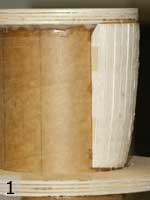
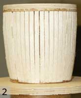
I started working from the aft end, first building up the nozzle detail on the outside of a 3.9" (98mm) MMT. (The prototype has a nozzle that comes to a narrower base at the aft end of the body, but I got as close as I could given the MMT.) A ½" plywood ring was bonded to the aft end of the MMT and pieces of balsa were cut to the rough profile of the curvature of the nozzle and tacked onto the MMT behind the ring with CyA (1). The balsa strips were applied in banks of 6, backed by tape to help keep them aligned (2). Finally, I sanded this to a smooth shape (3) Balsa is great for this application because it's easy to work and very light.
 |
 |
 |
In the picture below, you can see how I ran stringers between the two main centering rings (CRs) with T-nuts embedded in them, along with the other necessary structure.
Pretty complex, but this section has to perform many functions. The most obvious is as the MMT for the sustainer (main) motor, but also it needs to support the external structure for the drop-away boosters. The attachment points near the bottom (along with three which will go above the forward CR) are for mechanical attachment of the external structure yet to come.
 The main complication for the fin can is the attachment point for the fins.
Because the prototype does not have any fins, I wanted to use clear fins
(Lexan, a polycarbonate).
However, I wanted to keep the fins as small as possible and since I didn't know what
size was necessary until the rocket was almost finished and I could directly measure
the center of gravity (CG), I wanted them to be able to bolt into place afterwards.
This meant that there had to be access from inside the MMT to the bolts.
The main complication for the fin can is the attachment point for the fins.
Because the prototype does not have any fins, I wanted to use clear fins
(Lexan, a polycarbonate).
However, I wanted to keep the fins as small as possible and since I didn't know what
size was necessary until the rocket was almost finished and I could directly measure
the center of gravity (CG), I wanted them to be able to bolt into place afterwards.
This meant that there had to be access from inside the MMT to the bolts.
So, I cut access holes in the MMT itself so that the fins could be bolted into place once the rocket was completed. To the right you can see the jig I used to cut these holes. (Getting them this perfect is overkill, but I couldn't resist.)
Electronics Bay
The quest for the ultimate electronics bay continues. This main electronics bay (for sustainer dual deployment recovery) is a refinement of the one done for the Just Married rocket. Like that one, this one is built into a coupler which joins two sections that are bolted together in flight.
However, this one is simpler and has easier access to the inside. Of course, the 7.5" tubing makes this easier than 5.4" tubing, but I also left out the top plate in this version which makes the inside readily accessible.
 |
 |
In the photos above, you can see the window into the electronics bay to turn on the electronics (two altimeters and a camera). On the right, you can see the mounting board for the two altimeters (and R-DAS Kompact and a G-Wiz MC), their power buttons and buttons to control the video camera.
Note that unlike the Just Married rocket, this rocket has a hatch that covers the window, rather than having to slide the top section up. Just below the window, you can see a tubing "sill" that helps key the upper section to the lower. The upper section has a matching window cut out and slides down over this window, mating with the sill. The opening in the upper tube is covered with the hatch.
One other thing that's new for me is trying out the Rouse-Tech CO2 ejection system. This new product should help avoid the problems with black powder burning incompletely at high altitudes. Of course, this rocket isn't going to go as high as the Nike-Asp, but it's always better to be safe. The black tube in the photo is one of the CO2 cartridge holders.
Note that since I didn't have a flat seal at the top of the electronics bay, I needed to use an O-ring around the edge. In the photo on the right, you can see the 1/8" O-ring in a groove around the edge of the top plate. There is also an O-ring under the lip of the holder to keep a good seal and protect the electronics.
Booster Mounting Rings
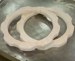
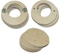
A key part of the sustainer is the mounting ring that supports the brackets to which the drop-away booster attach. These rings were cut out of ¾" plywood and mount around the outside of the sustainer.
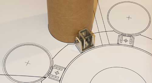
Above, you can see me test-fitting a 3.0" tube and the engaged brackets over a full-sized drawing of the airframe cross section and the ring. (You can download this drawing.)
Two ¾" plywood sheets were screwed together and the full-size template was applied to them with double-stick tape. This would allow the two rings to be exact duplicates as well as make it easy to drill the holes and cut the outside shape. The center hole was cut with a hole saw and the outside shape was cut on a band saw. Before the two sheets were separated, small pilot holes were drilled through the template where the holes would later be located.
Then the T-nuts were hammerd in place and the back covered over with epoxy to lock them in place.
 |
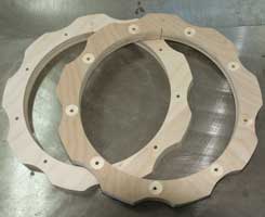 |
In the pictures above, you can see the rings after being cut out. On the left, right after the outside was cut and the two rings separated. On the right, after the holes for the drop-away brackets had been drilled and small pockets created on the top to bury the T-nut bases (seen on the top ring).
Launch Rail
The launch rail for this rocket proved a bit of a challege too. I couldn't use any of the standard rails because they are too large to fit between the boosters. (The blacksky rail is just a bit too large, especially because the rail isn't centered on the extrusion.) I discovered that Unistrut sells an aluminum channel system as well as their more common steel systems and that it comes in a 13/16" version. I chose the P6001 dual channel for its small size and lighter weight than the steel versions. (More information about their framing systems can be found on the Unistrut site.)
|
|
This rail is quite stiff, but I decided to use two rails and four buttons on this rocket to reduce the stress on the buttons (particularly the lateral stress when the rocket tries to "roll over" while on top of the rail). The prep of this rocket will take a while with all the boosters so having a good rail that supports it horizontally is important. The two rails attach on opposite sides of one of the boosters (and between two of the clear fins). See the drawing for more info.
Of course, a different size rail requires custom rail buttons so that was the next thing to figure out. (The 13/16" channel is small enough that the buttons for the standard (1 3/8") Unistrut channel are way too big.) There's not much to a rail button, but you can see my drawing here.
The Boosters
The drop-away boosters are what really makes this rocket special. There are nine of these babies in the rocket and so fabrication had to be planned out and all steps done with jigs for consistency. PDFs are available for the high-level drawing and the internal structure drawing (full size).
Drop-Away Clips
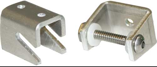
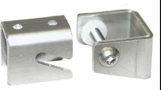
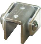
To make the boosters drop away, I had some small clips and matching brackets made at a local sheet metal shop. Below you can see the completed clips, first the clips separately, then (bottom left) in position to engage and finally (bottom right) engaged.
 |
||
 |
 |
|
The holes at the top of the clip and the back of the bracket are for attachment to the booster tubes and sustainer support ring respectively. The axle on which the clips hook is simply a #10 machine screw. The aluminum pieces are separated by Nylon washers to allow easy separation.
The pair of clips need to transmit the force of the booster motors to the sustainer so I wanted to make sure there was a solid anchor. The clips themselves are aluminum so mechanical mounting was necessary.
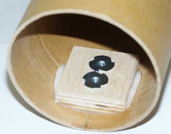
Each clip has two holes for #6 machine screws which screw into T-nuts embedded in ½" plywood anchor blocks epoxied to the inside of the booster tubes. On the right, you can see the aft anchor mounted inside a booster. This provides a solid mechanical joint and spreads the force out over a much larger area of the booster body tube. (A similar block is used for the forward clip as well.)
Like everything else for the boosters, the work was multiplied by nine (or 18). I used a couple of jigs to cut the angled shape for the side of the block which had to mate with the inside of the tube and to position the T-nut holes.
Angled Motor Mounts
Angling the motors of a cluster towards the center is a nice safety feature. If one doesn't light, the other still push towards the center of gravity of the whole rocket. According to Rockets of the World, the nozzles are angled 10° on the prototype. That's too much of an angle for a 38mm MMT inside the 3.0" booster tubes, but a 5° angle leaves room for 11" long MMTs.
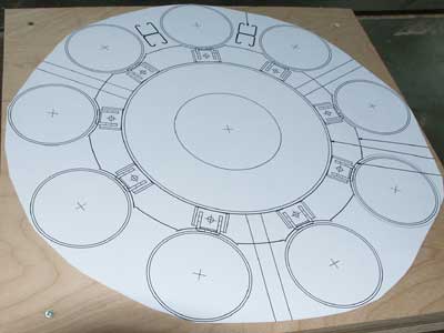
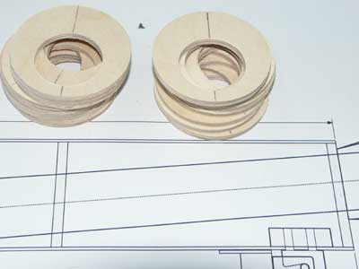
Of course, that means that custom centering rings must be made to accomodate the 5° angle. Below you can see the jig I used to cut the holes in standard 3.0" bulkheads. (Since 18 identical CRs had to be made, a jig was a necessaity.)
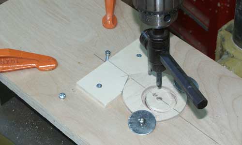
The finished centering rings with the angled hole on top of the full-size booster plan. Note that the vertical axis was marked on the CRs at the time each hole was cut. This allows them to be aligned with the booster.
Because the nozzles are angled 10° and the MMTs are angled 5°, the aft end of the MMT makes a 5° angle with the aft end of the nozzle. The booster internals drawing makes this clearer (and is partly shown above).
Nozzles and Nosecones
The six ground-started boosters have smaller nozzles than the three air-started ones. (The larger nozzles are more effective in a thinner atmosphere.) I decided to model this detail as well and so two molded parts were needed.
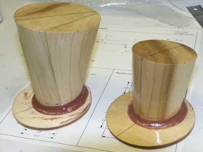
 Above you can see the parts which make the two mold plugs freshly assembled and sealed with epoxy.
(The nozzles were simple conical turnings, with the base cut at a 10° angle.)
The parts include the nozzle and the aft end of the booster which bonds to the aft centering ring.
Above you can see the parts which make the two mold plugs freshly assembled and sealed with epoxy.
(The nozzles were simple conical turnings, with the base cut at a 10° angle.)
The parts include the nozzle and the aft end of the booster which bonds to the aft centering ring.
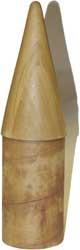
To the right is the blank for the booster nose cone. Note that I just had the conical part turned and used an actual coupler for the part that will socket into the body tube.
All three parts are glued up and painted with epoxy to seal the wood. Making the "blanks" is the first step in making a fiberglass mold. The (positive) blank forms the shape, a (negative) mold is made from the blank and the parts are finally made from the mold. For detailed information on this process, see my Nike-Asp page.
Electronics Bays
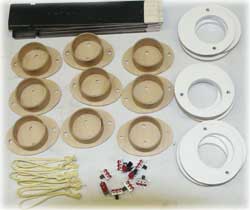
Each booster had its own recovery electronics. It might have been possible to tie the booster recovery into the sustainer electronics, but I wanted to keep things as simple and modular as possible. I chose G-Wiz LCs for the electronics because they are thin and relatively cheap and since the boosters are apogee-only deployment a barometric sensor isn't necessary.
On the right, you can see the rings that mount inside the booster body tubes with holes cut in them for a short section of 38mm tube. Below the two stacks of rings is a stack of oval caps for the electronics bays. These are mounted to the top of the bay and provide the seal.
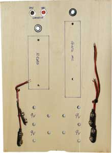
Here are all the parts for all nine electronics bays laid out on the work table:
|
The mounting boards were sprayed with flat black paint to make it easier to see the
switches. (The switch actuators are painted white.)
Here the ¾" pieces of 38mm tubes have been tacked to the caps with CyA. The rings were painted with epoxy (dyed white) to seal them from the ejection charge residue. Rather than using eye bolts or similar hardware, I used loops of eighth-inch aramid cord as recovery attachment points. For power I used standard sngle-pole slide switches. |
The mounting boards were tacked to the caps and rings with CyA and then epoxied into place. Once the epoxy was dry, the switches were mounted with screws and the wires soldered to them.
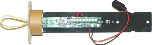
And finally, above is a single completed bay with its G-Wiz mounted to the board. The only thing missing is the 9v batter which is mounted to the right (below in flight) the power switch. The two holes and two notches are for tie straps to hold the battery in place.
Historical Info.
Text and picture from Rockets of the World (Third Edition, page 238).
Evolution of the Delta continued through the 1970's, as all stages and boosters of the vehicle grew. Nine solid boosters became the norm. As the 1980's dawned, NASA hoped to replace expendable boosters, including the Delta, with the reusable Space Shuttle. Delta production wound down, but the 1986 Challenger explosion changed everything. The Air Force was particularly interested in maintaining an independent route to space via expendable boosters. In January of 1987, the. Air Force awarded McDonnell-Douglas a contract to produce an even larger version of the Delta, the Delta II, to orbit its Navstar II Global Positioning Satellites (GPS).
Nine Castor 4A boosters, more powerful than previous versions, augment the Thor first stage of the Delta II. The first stage itself is stretched to hold more liquid oxygen and kerosene than its predecessors. Aerojet still provides the nitrogen tetroxide and unsymmetrical dimethyl hydrazine-burning restartable second stage engine. Thiokol produces the PAM-D solid third stage.
On February 14, 1989, the first Delta II lifted off from Cape Canaveral carrying the first operational Navstar. The booster successfully launched the satellite into orbit.
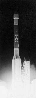
For all the use the GPS satellites have seen, the Delta II has launched an even more famous spacecraft. Early in the morning of December 4, 1996, a Delta II, model 7925A, launched Mars Pathfinder into a solar orbit that would intercept the Red Planet on July 4, 1997. The balloon-cushioned probe landed, unfolded, and released the Sojourner rover to probe the surface. For weeks the tiny vehicle captured the imaginations of Earthlings as it photographed and analyzed rocks and soil.
The Delta II has launched more probes into deep space, and the Delta II and the new Delta III will continue to fly well into the 21st century.
Above right, A delta II boosts Mars Pathfinder with its tiny Sojourner rover towards Mars in the early morning hours of December 4, 1996 (NASA photo KSC-96PC-1324).
Delta II Specifications
| liftoff weight | 483,700 lb (219,900 Kg) |
| Solid Boosters: | |
|---|---|
| Thrust | 9 x 103,000 lb (458,000N) |
| Duration | 56 sec |
| Impulse | 5,800,000 lb-sec (26,000,000 N-sec) |
| NAR designation | 9 x Y 460,000 |
| Stage 1: | |
| Thrust | 207,000 lb (921,000 N) |
| Duration | 265 sec |
| Impulse | 54,900,000 lb-sec (25,700,000 N-sec) |
| NAR designation | AB 920,000 |
| Stage 2: | |
| Thrust | 10,000 lb (44,000 N) |
| Duration | 432 sec |
| Impulse | 4,300,000 lb-sec (19,000,000 N-sec) |
| NAR designation | X 45,000 |
| Stage 3: | |
| Payload | weight 3,190-8,780 lb (1,450-3,990 Kg) |
| Thrust | 15,000 lbs (67,000 N) |
| Duration | 87 sec |
| Impulse | 1,300,000 lb-sec (5,800,000 N-sec) |
| NAR designation | W 67,000 |