Wac Corporal
In 2004 my local club, AERO-PAC, decided to do a group project. My first suggestion was a full-size Wac Corporal model to celebrate the 60th anniversary of the first full-size launch (on September 26, 1945). Eventually, another idea was chosen for the group project, but I still wanted to build the Wac and it became a personal project.
The Wac Corporal became the first U.S. rocket to reach space (50 miles on May 22, 1946) and was the high point of the home-grown U.S. rocket program (before the V2 rockets and German scientists came in after WW II).
I mulled over the idea in the background for a few months, but had been too busy with moving to do much actual work. In late December 2004, I started design in earnest. The goal was to have it realy to fly at XPRS 2005, on the weekend of September 24th on certified motors, or perhaps on Monday the 26th with EX motors.
In 2016 we moved and all projects that had been sitting for more than five years without progress were abandoned. This one one of them.
The Pictures
The Design
I haven't modeled a rocket at full-scale before and this rocket is small enough that it makes a good candidate to model at 100%. The Wac Corporal sustainer is 194" (16.2', 4.9m) tall, the Tiny Tim booster is 88" (7.3', 2.2m) tall, and the full rocket is 289" (24', 7.3m) tall.
Here are the primary drawings showing the three most interesting parts of the rocket (Acrobat PDF files):
 Overall Overall |
 Interstage Interstage |
 Booster Booster |
The most tricky thing for this rocket was the interstage, which is doubly challenging because it needs to withstand some severe heating when the sustainer motors fire. In the prototype, the booster burned for only 0.6s and liftoff triggered the sustainer to fire (a hypergolic motor using RFNA). Obviously, the interstage could not withstand the full force of the sustainer motors, but I wanted it to fall away just as the sustainer was coming up to pressure.
Interstage
The interstage had to be built to support the weight of the rocket, keep the sections in alignment, and withstand the coming-up-to-pressure heat of the sustainer motors. Interestingly, when modeling at 100% you get some of the same chalenges as the prototype, although in less extreme forms.
Here is a drawing showing the components of the interstage: Acrobat PDF.
Airframe Tubing
Clearly, I would need to make my own tubing. The O.D. of the sustainer is 12" and the booster is 11¾". The tubing would be made completely from scratch; rolled on a mandrel using carbon fiber and fiberglass with a thin core. The longest tube I need is 91" long which demands a really big tube!
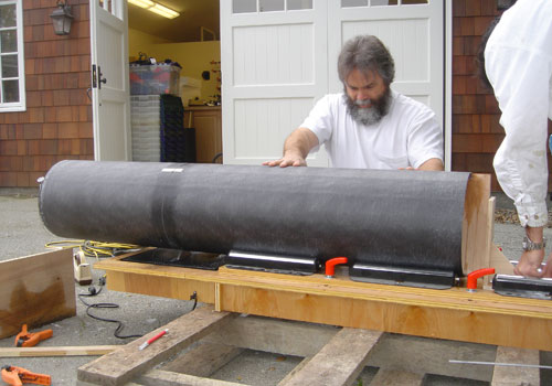
The mandrel would have been too costly made in aluminum so I decided to use a cardboard tube. In order to be able to release the part, I cut a slit along the length of the mandrel tube and inserted a wooden strip. The strip could then be pull out, the mandrel tube would collapse, and the part would slip off the mandrel.
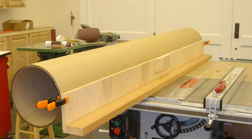
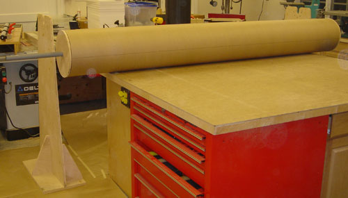
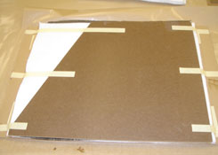
In the photo above, I am about to cut the slit in the length of the mandrel tube. This is an 8' long tube, 11¾" OD, made for me by Yazoo Mills.
 |
 |
|
|
On the left you can see the insides of the mandrel.
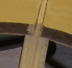
The slit is filled with a tongue of wood that is part of interior bracing to support the
cardboard mandrel around the central rod.
Above is a closeup of the slit in the cardboard and the tongue that fills it. (All this to keep it from bowing under the weight of the coardboard tube!) |
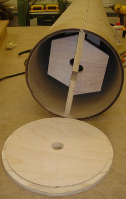
The mandrel body is made from the cardboard tube, supported on the stands by a rod. Two caps fit into the ends of the mandrel tube to keep it round and keep the rod centered. Also, wooden structures slide inside the tube to keep the rod straight and to support the tongue that fills the slot in the tube.
Above you can see the mandrel assembled and ready for the tube to be rolled onto it. To the left, and slightly behind, you can see one of the stands that holds the mandrel while it's in use.
These tubes are too big for one person to roll so a few friends from AERO-PAC came over to help me. We made the first tube (60" long) on Monday, February 21st (Presidents' Day 2005).
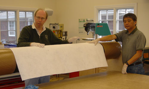
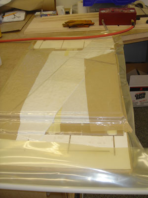
The first step was to tape over the slit and cover the mandrel with release. Then, the inner layers were applied. In the picture above, you can see the inner two layers of carbon fiber already applied and the Baltec core mat going on.
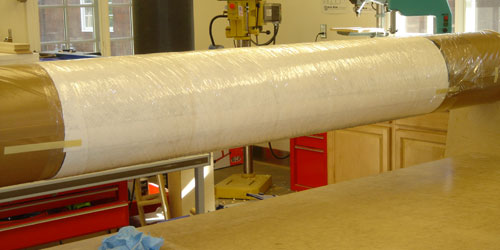
Once the inner layers were done, the whole thing was wrapped with stretch wrap to hold it together until the epoxy went "green."
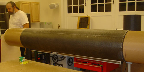
Four hours later, the epoxy was ready for the outer layer. First, I took off the plastic wrap and trimmed the Baltec overlap, then it was time to apply the outer wraps of carbon fiber and a final wrap of fiberglass.
I was anxious to see how the tube came out and whether or not I could release it easily. After work Tuesday night, I went out in the shop to see what we made.
I was able to pull out the support framework from one end. (The other support was locked in by the tape along the slot.) Squeezing the end of the cardboard tube and a light tap and the tube popped loose. My wife held the tube and I pulled out the mandrel easy as pie.
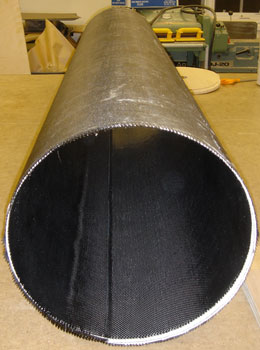
Whew; I was very glad to see the tube come free of the mandrel so easily since I still had two more sections to make! (This first 60" section was enough for the aft end of the sustainer and the forward end of the booster.)
On the right you can see the results of our work. Thanks Paul, Mike, Own and Dan!
Making the tubes is only the first step. After that, the ends need to be cut off squarely. This rocket was the inspiration for my tile saw tube cutting jig. Above you can see Erik and Mike making the first end cut on one of the Wac Corporal tubes.
Here there are making the second cut, this time cutting the tube to length (37½" for the aft end of the sustainer). Note how the right end is already cut smooth and square.

We cut two sections out of the first tube, one 37½" long for the aft end of the sustainer and one 18" long for the electronics bay of the booster. (Those were the two "short" pieces on this rocket.)
We also cut the inner tube for the aft end of the sustainer to final length. (This is the tube to which the fins are attached, and provides the necessary inner structure for the sustainer boat tail.)
On the right, you can see all three completed sections of tubing.
These large tubes are a lot of work, and are too much to do alone, but as the song goes: "with a little help from my friends..."
For more information on this tube cutting jig, see my Cheap Tube Saw page. Note that we're using a wet cutting tile saw and as a result aren't breathing any of the dust from cutting these large tubes.
The first tube proved that we could do it, but there were still two more tubes to lay up and the next one would be a beast. The main section of the sustainer was a single airframe tube, which would need to be 91" long!
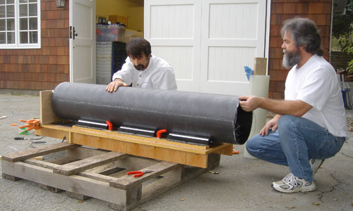
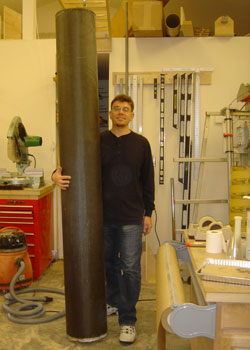
The second tube building session produced a tube as near to 8' as possible. (We ended up with 93" plus some ragged edges where there was extra fiberglass.) On the left you can see me holding this monster tube.
This is by far the largest all composite rocket tube I have seen used for hobby rocketry and it sure is impressive in person.
And best of all, it only weighs 10¼ pounds! That's just 1.3lbs/ft; much lighter than any hobby rocket tubing of similar size.
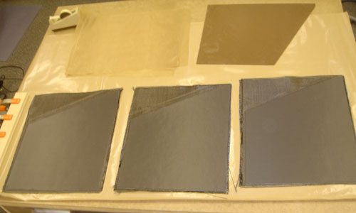
The Fins
The fins were done using the familiar composite construction using foam and carbon fiber.
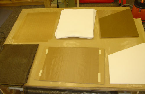
Above are the pieces laid out for the three Wac Corporal fins:
- Porous release film (6)
- Breather cloth (6)
- Non-porous release film (2)
- Masonite cauls (3)
- Carbon fiber cloth (6)
- base board
- 2mm Rohacell® cores (3)
 |
 |
 The three fins were laid up at once and bagged at the same time.
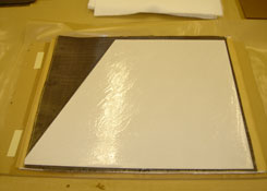
Because these fins are too large to lay out separately in the bag, I stacked them up with Masonite cauls between each one and on top. This worked out very well and I was able to make all three fin cores at once.
In the pictures above, you can see the first fin being laid out on the base board. On the left, the bottom piece of carbon fiber cloth and the first core are set out and the top of the core is coated with epoxy for the second piece of cloth. On the right, you can see the caul on top of the first fin core.
To the right are the three cores stacked up and under vacuum in a small veneer press.
Below you can see the three fin cores out of the bag and ready for the profiles to be applied. (The carbon fiber cloth was cut in rectangles, but the cores show the outline of the eventual fin shape.)
The Nosecone
The nose cone also needed to be custom made. The nose here is a true cone, which makes turning the mold plug easier. However, the nose is very large, making it difficult to find a lathe large enough. Here is a drawing of the plug itself.
The material out of which to make the plug is also an issue. I was hoping to use something better than wood, since wood tends to split and expand (as I found out with the Nike-Asp nose). However, other materials are very heavy and/or expensive.
Tiny Tim Booster
The prototype Tiny Tim booster was slightly smaller in diameter than the sustainer (11¾" vs. 12"). However, for simplicity I decided to model them both using the same tubing size since that would allow me to use the same mandrel to produce the tubing.
The interesting parts of the booster are the forward end with the interstage and the aft end with the 25 motor tubes. Here is a drawing showing the booster details (forward and aft ends): Acrobat PDF.
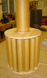
Booster Forward End
The forward end of the booster has to support the framework of the interstage and provide the electronics bay for booster recovery.
Booster Aft End
The aft end ended up with 24 motor mount tubes: 1 central 98mm tube and 24 38mm tubes in two circles. The central MMT is just for a backup and I'm not actually planning to use it. The 24 38mm MMTs are to accomodate short-burning motors that will give a prototypical short burn/high thrust profile to the booster. (The prototype Tiny Tim booster actually had 24 nozzles so this works out nicely.)
Like the sustainer, the booster thrust plate is actually aluminum. An aluminum plate was made using a 2D laser cutting system, providing me with a very accurate template for making the plywood centering rings and other parts. The plate would also be the aft skin of the rocket, protecting it from the high base drag such a large cross-section would generate.
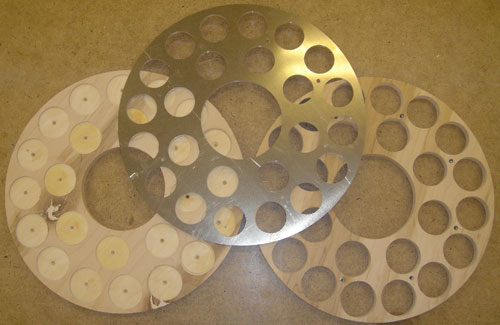
Above you can see the aluminum ring on top of the two ½" plywood rings I produced. These two plywood rings form the two centering rings that hold the MMTs.
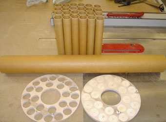 |
 |
Then, it was time to glue it all up. That was a chore as you can imagine; lining up the 24 MMTs with the holes and sockets in both rings was painstaking. Above you can see the parts on the left and the whole thing glued up and ready to install on the right.
Historical Info
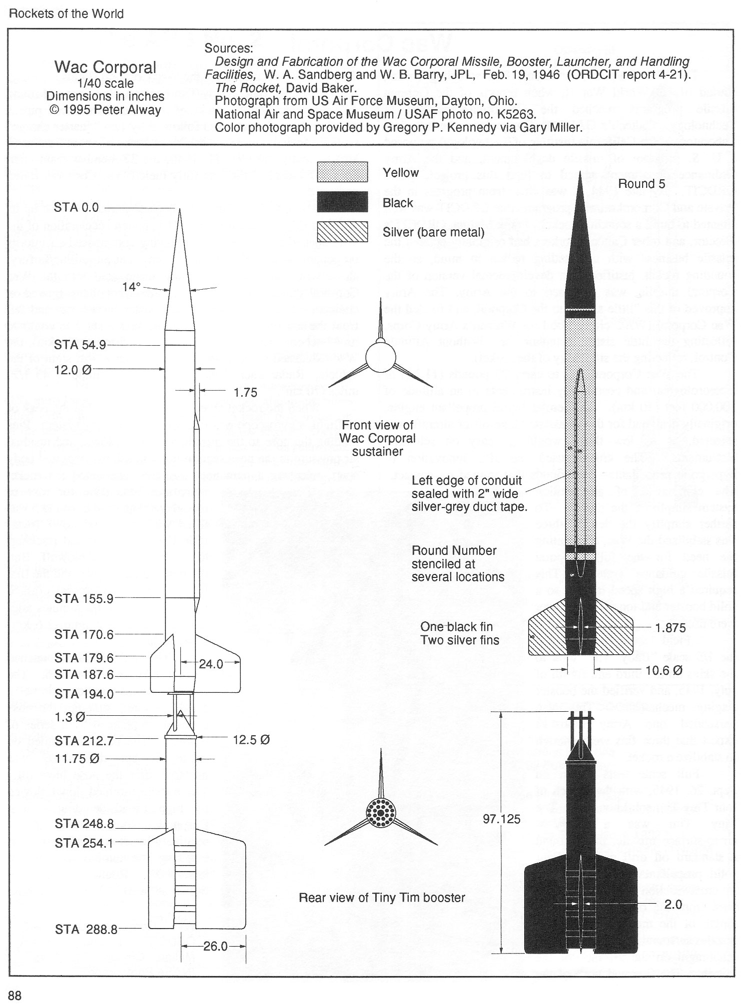
Text from Rockets of the World. (The Wac Corporal article starts on page 87 of the third edition.) I have also scanned in Peter Alway's drawing for reference.
The Wac Corporal, America's first sounding rocket, started life in World War II, when reports of the German missile programs reached the California Institute of Technology. Caltech's GALCIT (Guggenheim Aeronautical Laboratory at the California Institute of Technology) proposed a U. S. program of missile development, and the Army Ordinance department agreed to fund this project, called ORDCIT. By late 1944, it was clear from progress in the Private and Corporal missile programs that ORDCIT was well situated to build a sounding rocket. Frank Malina, ORDCIT's director, and other Caltech workers had originally entered the missile business with a sounding rocket in mind, so the sounding rocket, justified as a developmental version of the Corporal missile, was proposed to the Army. The Army approved of this "little sister" to the Corporal, and funded the Wac Corporal (WAC either stood for Women's Army Corps, reflecting the little sister metaphor, or Without Attitude Control, reflecting the simplicity of the rocket).
The Wac Corporal was to carry 25 pounds (11 kg) of meteorological and cosmic ray instruments to an altitude of 100,000 feet (30 km). An Aerojet liquid propellant engine, originally designed for the jet assisted take-off of aircraft, was selected, as its low thrust would be easy on scientific instruments. The engine used the JPL innovation of hypergolic propellants-compounds that ignited on contact. The elimination of an ignition system simplified the design. To further simplify the design, three fins stabilized the Wac, eliminating the need for the full Corporal missile guidance system. This required a high speed launch, so a solid booster and long launch tower were used.
Field testing began when the 1/5 scale "Baby Wac" took to the skies on the third and fourth of July, 1945, and verified the booster staging mechanism. This also persuaded one Army ballistics expert that three fins were enough to stabilize a rocket.
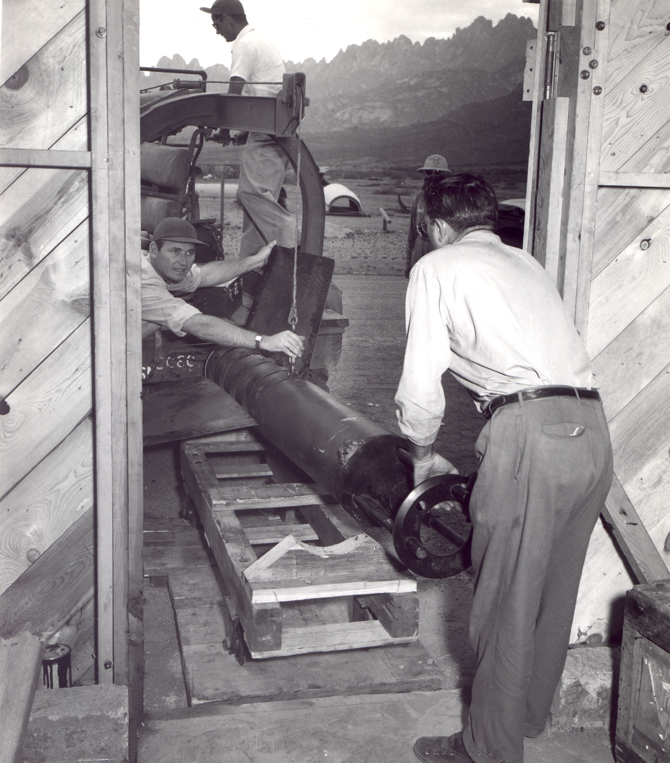
Full scale tests began on Sept. 26, 1945, with the launch of four Tiny Tim solid boosters. The Tiny Tim was a Navy air-to-surface missile, built around a standard oil drill casing. Four solid propellant grains, cruciform in cross section and designed to burn from the outside in, ran the length of the motor. Two dozen nozzles surrounded a pressure relief diaphragm on the aft face of the missile. The fins and nose of the Tiny Tim were replaced for the Wac Corporal flights.
The next day, a Tiny Tim boosted Wac Corporal round 1, a dummy vehicle made of concrete-filled steel pipe. Another dummy flight was followed by two "quarter-charge" partially fueled missiles, reaching altitudes of about 5 miles (8 km). Finally, on Oct. 11, 1945, the 37-member team from GALCIT launched the first fully fueled Wac Corporal, round number 5.
Ignition of the Tiny Tim booster started the Wac up its 100 foot (30 m) launch tower. The sudden acceleration of the Wac opened an inertia valve, allowing compressed air into its propellant tanks. This action in turn sent an aniline/furfuryl alcohol mixture and red fuming nitric acid into the Wac Corporal's combustion chamber. These propellants ignited on contact. After 0.6 seconds, the booster burned out and fell from the sustainer, leaving the liquid fueled stage to continue its 47-second burn. At an altitude of 15 miles (24 km), the Wac exhausted its fuel, and the ground crew lost sight of the vehicle. Radar tracked the vehicle to an altitude of 43 1/2 miles (70 km).
When the rocket arced over to horizontal at the peak of its flight, a gyroscope was to trigger the recovery system. Pins holding the nose to the missile would be blown, and residual air pressure in the nose section was to push the nose and body apart, releasing a parachute. A cord connected the rocket body and nose cone for ease of recovery. The nose of round 5 was filled with radar "window" (radar reflective material to aid tracking) to be ejected at nose blowoff. But, the nose failed to eject, and the first full-charge Wac Corporal crashed into the ground 7 1/2 minutes after launch, less than a mile (1.6 km) from the launcher.
The GALCIT team launched five more Wacs in late 1945. The Wac Corporal proved to be a reliable rocket, although the nose cones were plagued by a series of failures. The parachute failed on round 6, but the rocket was unstable after the nose blew off. The missile tumbled down slowed by high broadside drag. Wac Corporal No. 6 was found relatively intact on the desert floor, inspiring the tumble recovery of later V-2's. Round 7's parachute failed as well. Round 8's nose ejected as it left the tower, but the rocket continued on an otherwise successful flight. Before the launch of round 9, a leak in one valve had led to partial opening of the propellant valve. This led to premature combustion in the engine. The launch crew hastily fired the booster for an emergency launching. This action fully ignited the Wac Corporal sustainer which then continued on a normal ascent, followed by a failure of the nose to eject. Round 10 flew at night. Its flight was marred only when its nose did not eject. By October 25, the initial development flights were complete.
Five more Wac Corporals were built, two of which flew in May of 1946 to the Wac's highest and lowest altitudes. One was launched on May 10, a few hours after the demonstration launch of a captured V-2. This Wac was not as successful as the previous rounds, reaching only 10 miles (16 km). Another, launched May 22, reached an altitude of 50 miles (80 km), and could thus be regarded as the first American rocket to enter space.
After the supply of Wac Corporals was depleted, the Caltech team returned to their drawing boards to develop an improved rocket, the Wac B. Through changes in materials and design, the engine was lightened from 50 to 12 pounds, the structure of the missile was modified, and a new 5-channel telemetry system was added. About a half dozen Wac B vehicles were flown in December 1946 and February and March of 1947. One Wac B, launched from White Sands on Feb. 17, 1947 reached an altitude of 45 miles (72 km).
By March 31, 1947, the Wac Corporal development testing was complete. The Wac Corporal program had seen 17 launches. In addition to various tracking aids, the payload of the Wac had been outfitted to study temperatures, pressures, and sky brightness at altitudes previously beyond the range of human measurement. Later that year, Aerojet engineering, a commercial spinoff of the Caltech team, replaced the Wac Corporal with the Aerobee.
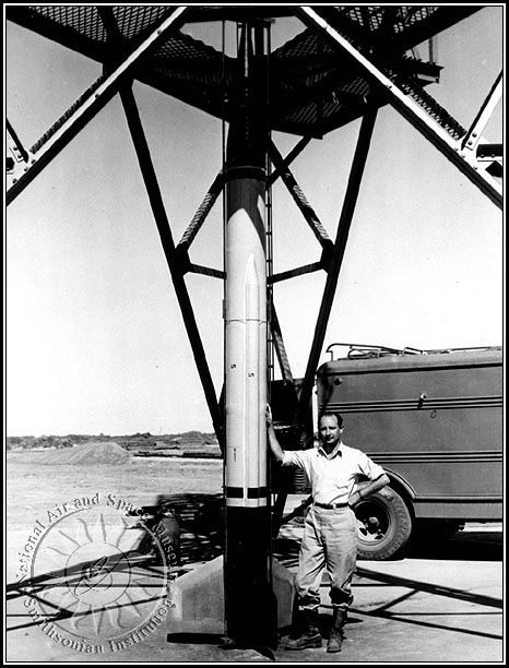
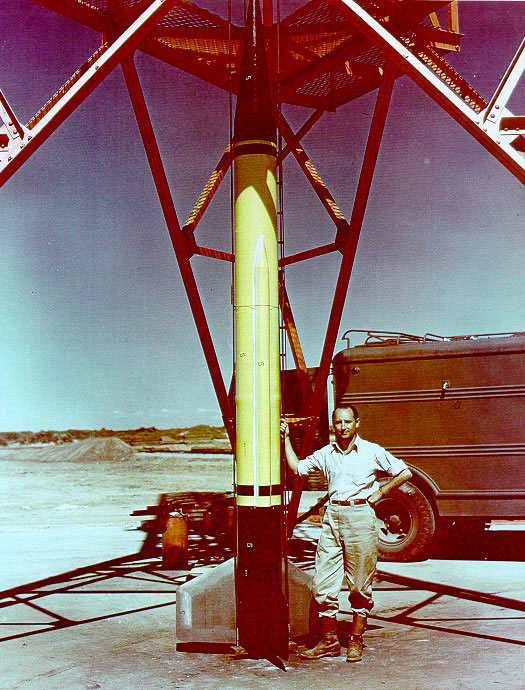
Wac Corporal no. 5 with ORDCIT Director, Frank Malina, October 11, 1945
(NASA photograph)
| Booster: | ||
|---|---|---|
| Loaded weight | 759.2 lb (345 kg) | |
| Propellant weight | 148.7 lb (67.6 kg) | |
| Thrust | 50,000 lb (220,000 N) | |
| Duration | 0.6 sec | |
| Impulse | 30,000 lb-sec (130,000 N-sec) | |
| NAR designation | 0220,000-0 | |
| Sustainer: | ||
| Empty weight | 296.7 lb (135 kg) | |
| Loaded weight | 690.7 lb (313 kg) | |
| Thrust | 1,500 lb (6,700 N) | |
| Duration | 47 sec | |
| Impulse | 67,000 lb-sec (300,000 N-sec) | |
| NAR designation | R 6,600-0 | |
Paul Hopkins sent me these two color pictures of the Wac Corporal (with Frank Molina posing along side). (Click on either photo for the original versions I received.)
|

|
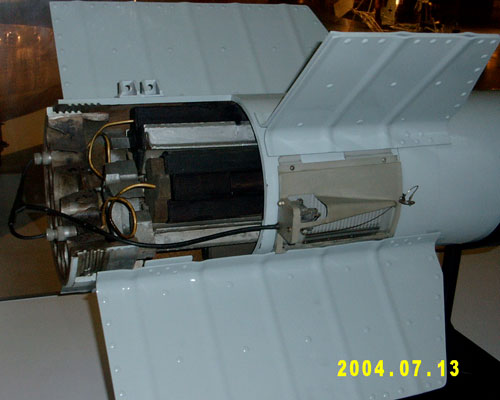
I also found this picture taken by Phil Callihan of a Tiny Tim missile in a museum:
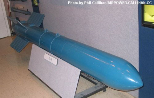
Paul Hopkins sent me a set of pictures he took at the National Air and Space Museum of a display model of the Tiny Tim. This one shows the fins nicely:
Unfortunately, it appears that the Tiny Tim fins were replaced with larger ones for the Wac Corporal booster. The drawings in Rockets of the World show an airfoiled shape and the second photo seems to confirm this (pages 88 & 89 in the third edition).
These give me the color scheme; the one on the right seems to show the colors a bit better. Also notice that you can see the profile of the fins in the left photo.
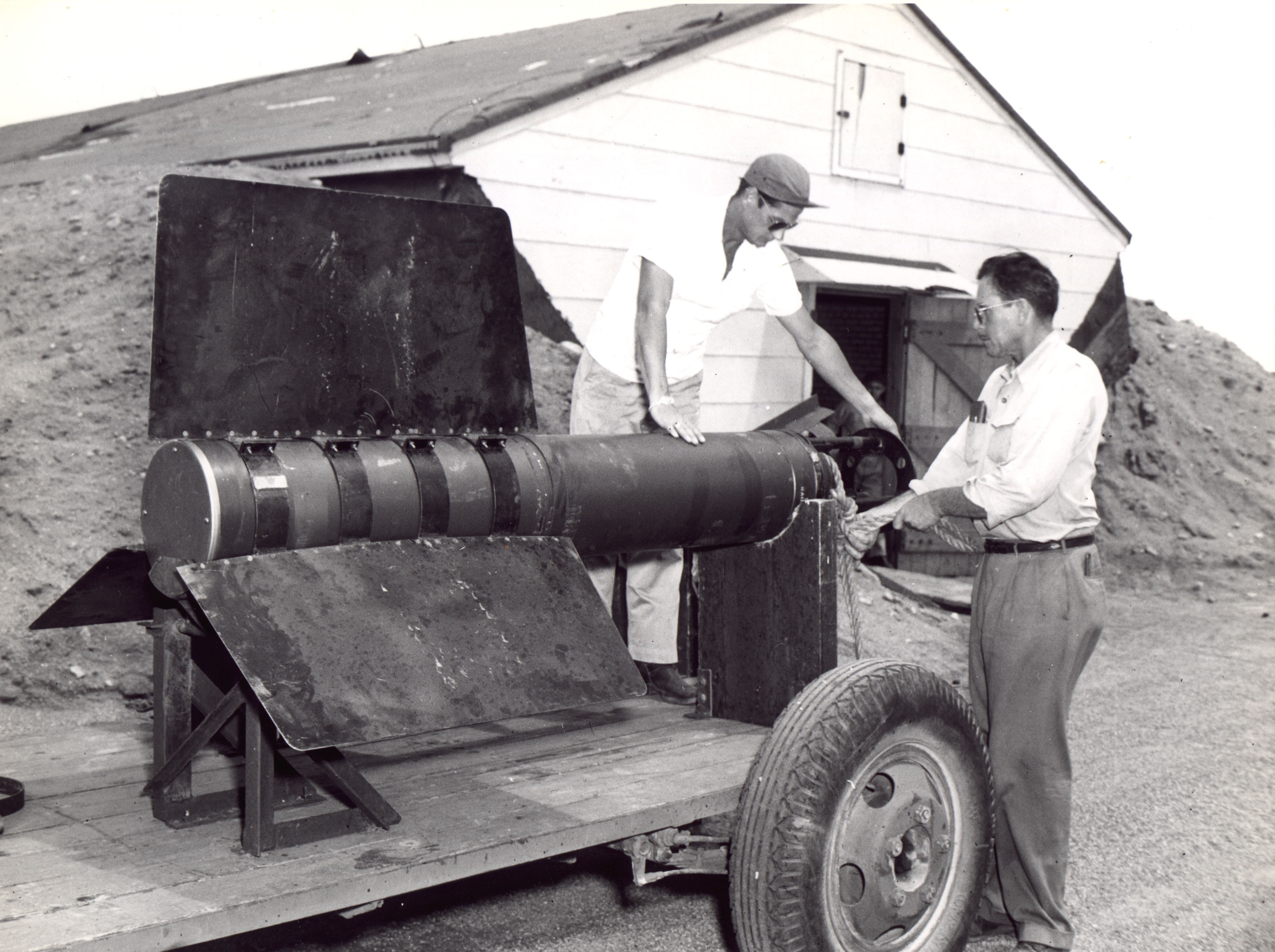
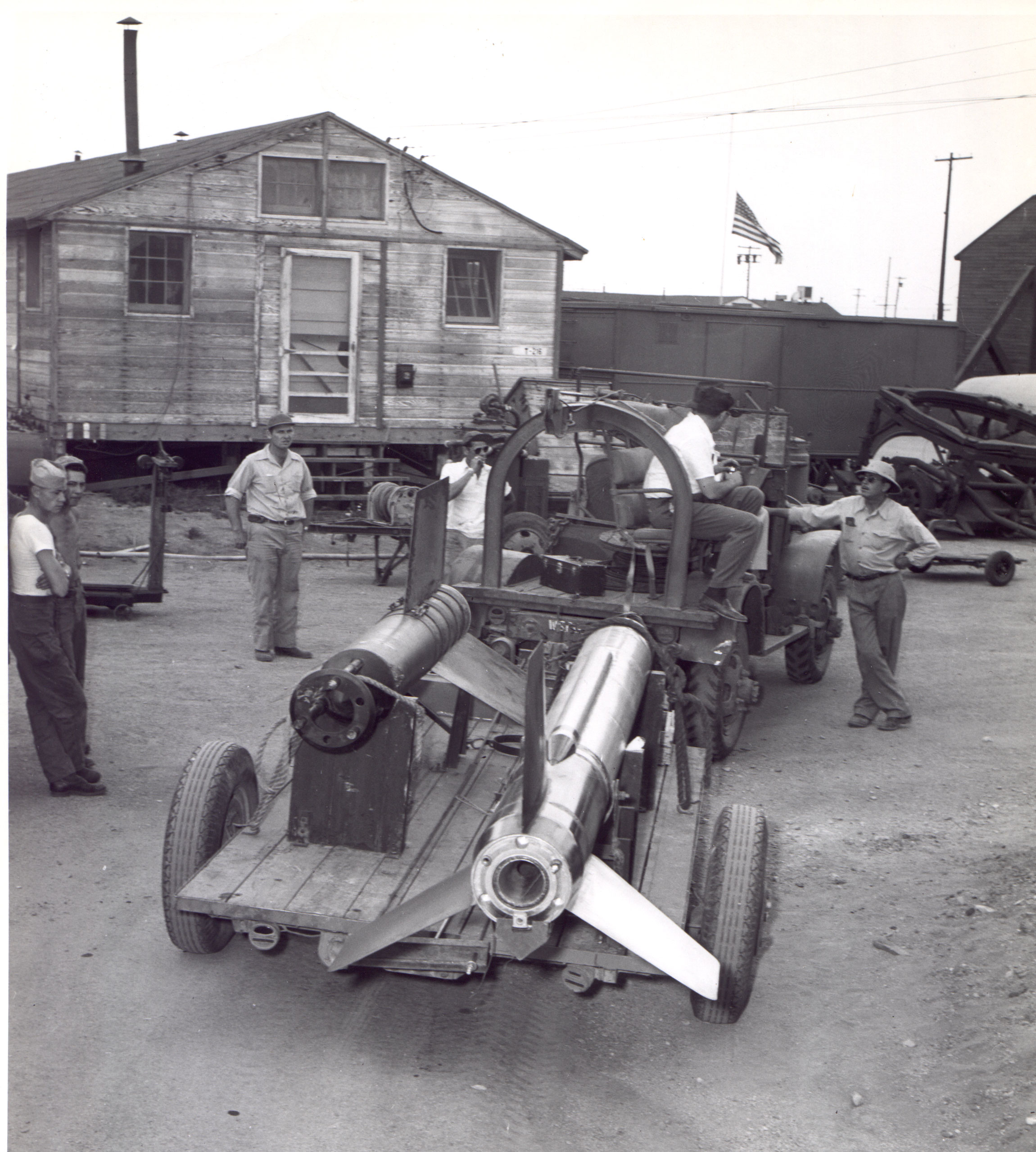
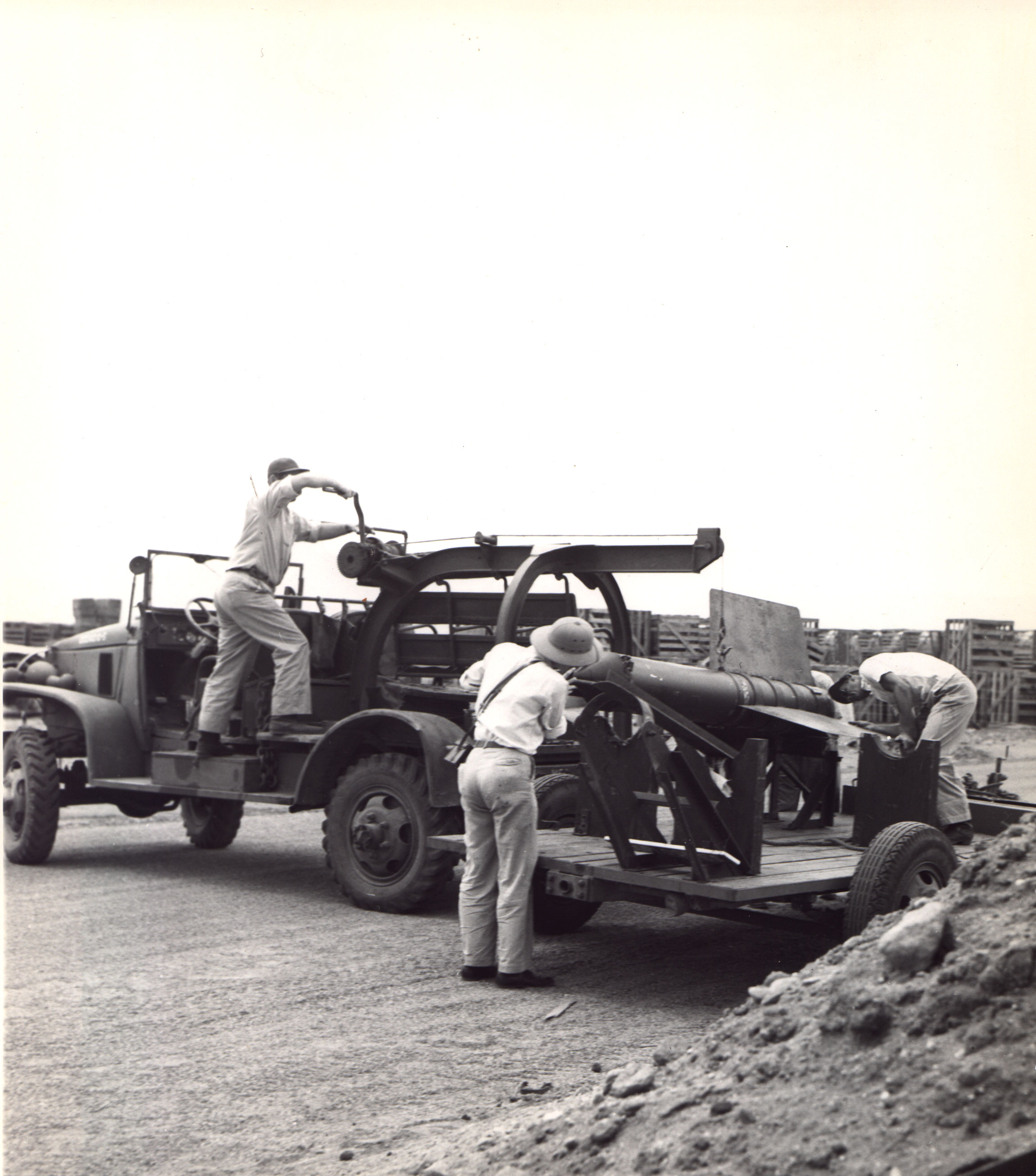
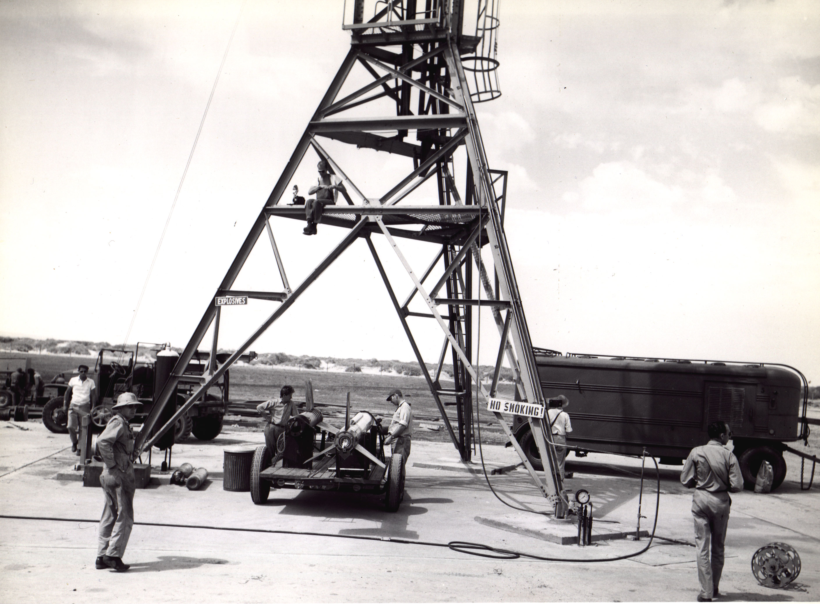
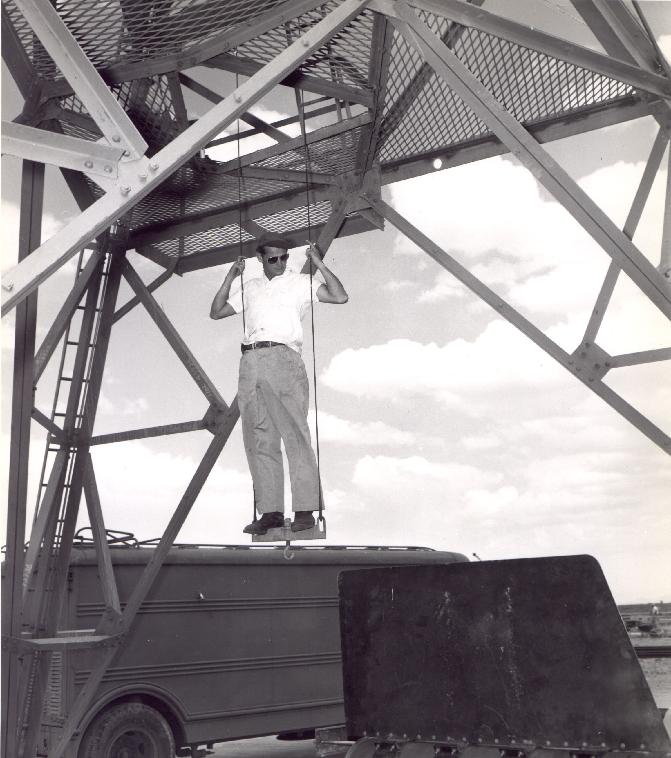
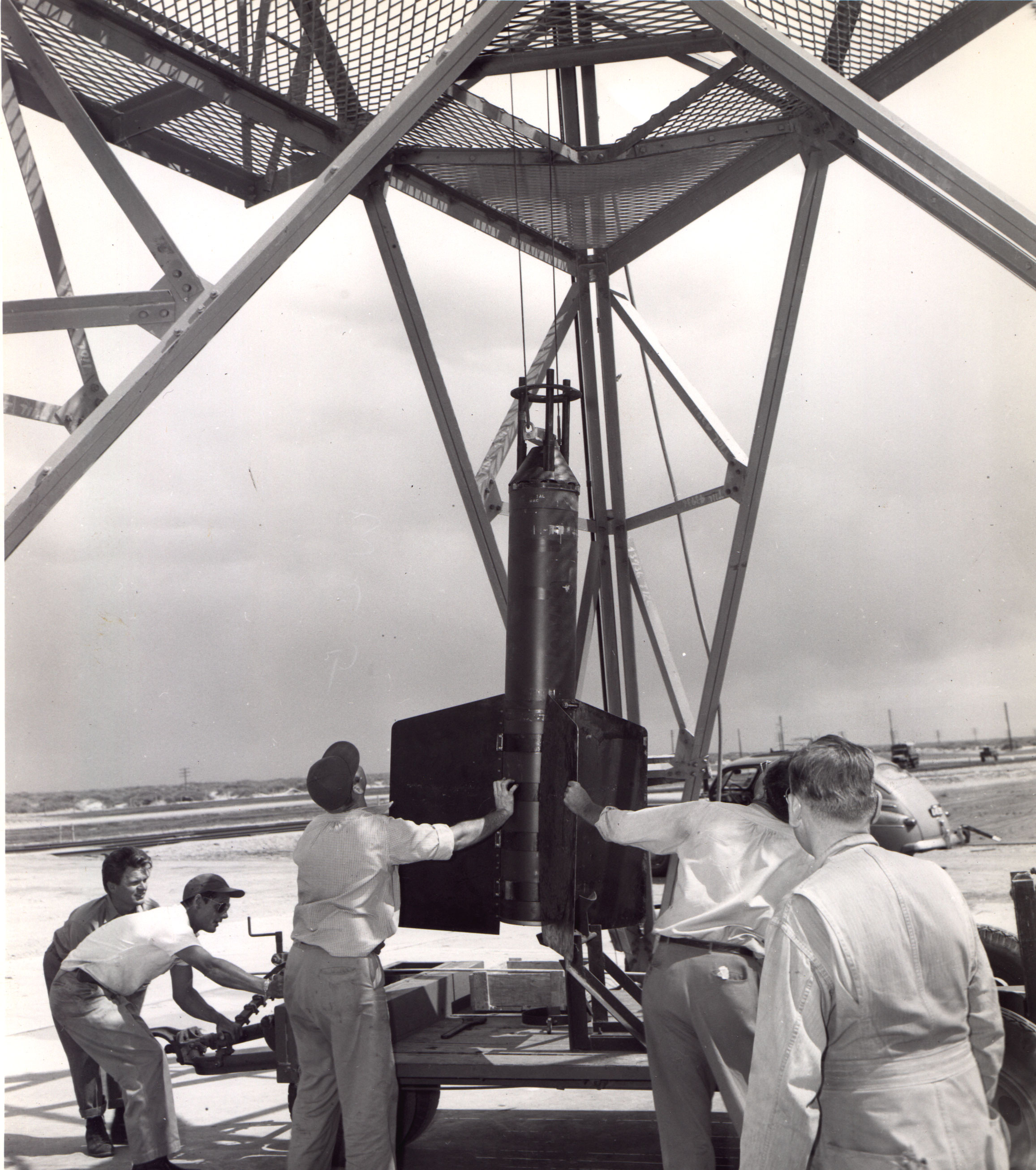
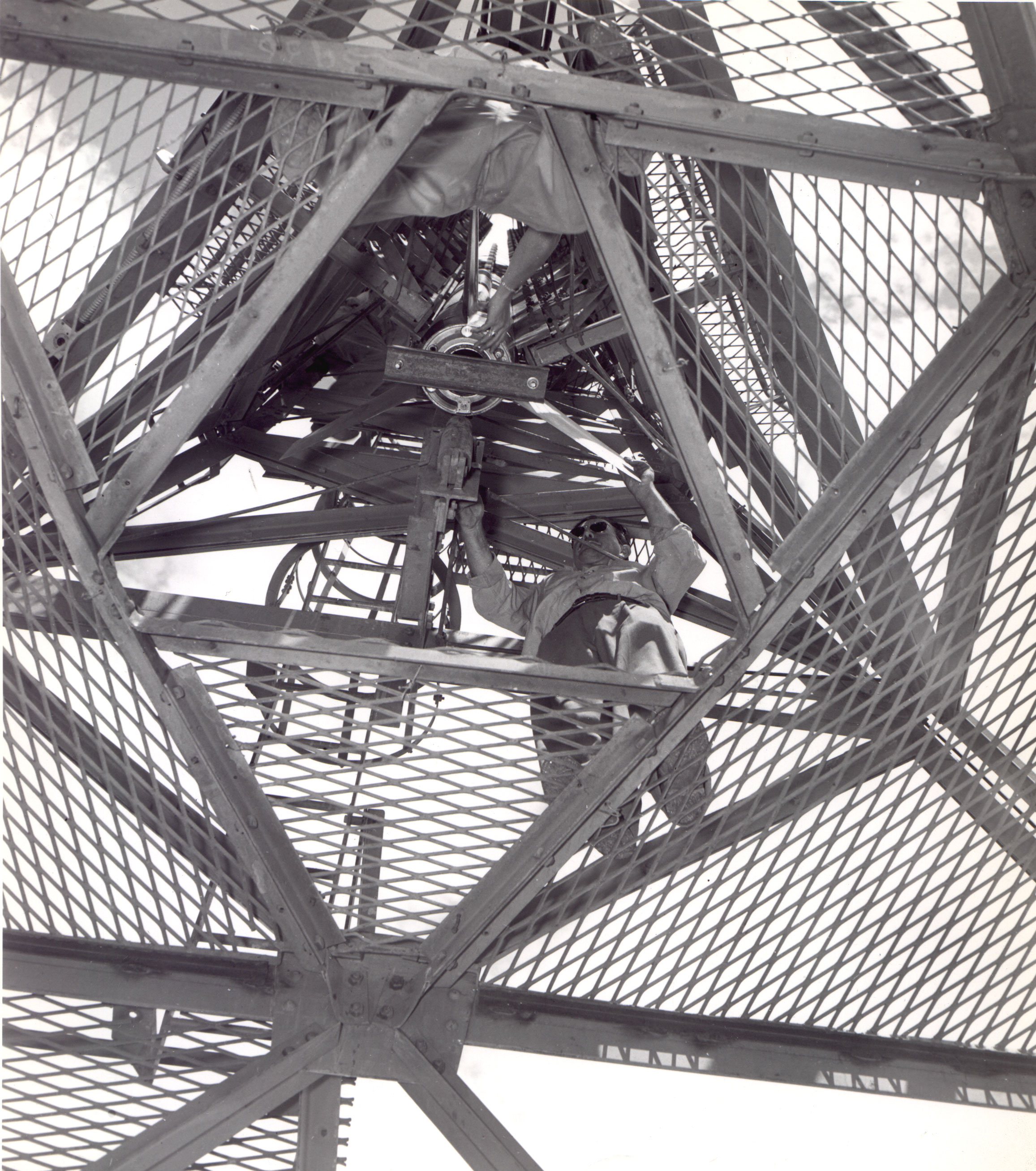
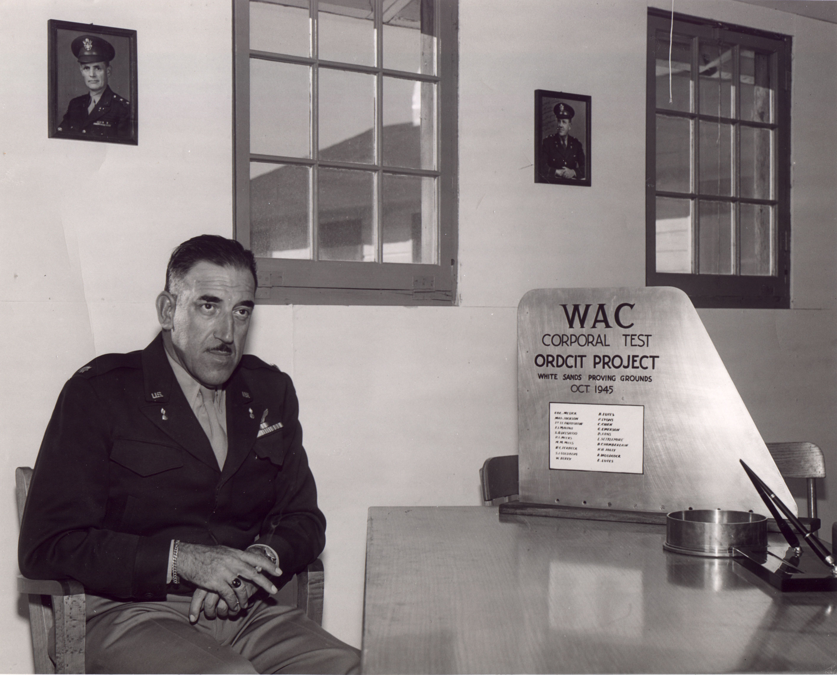
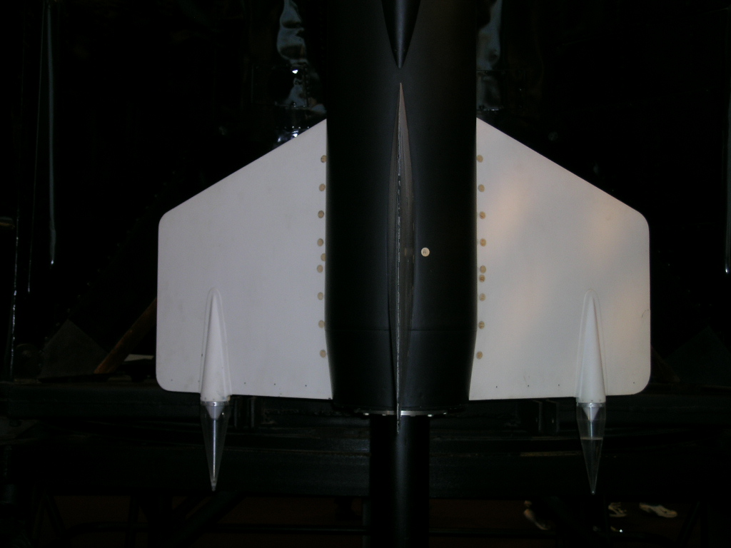
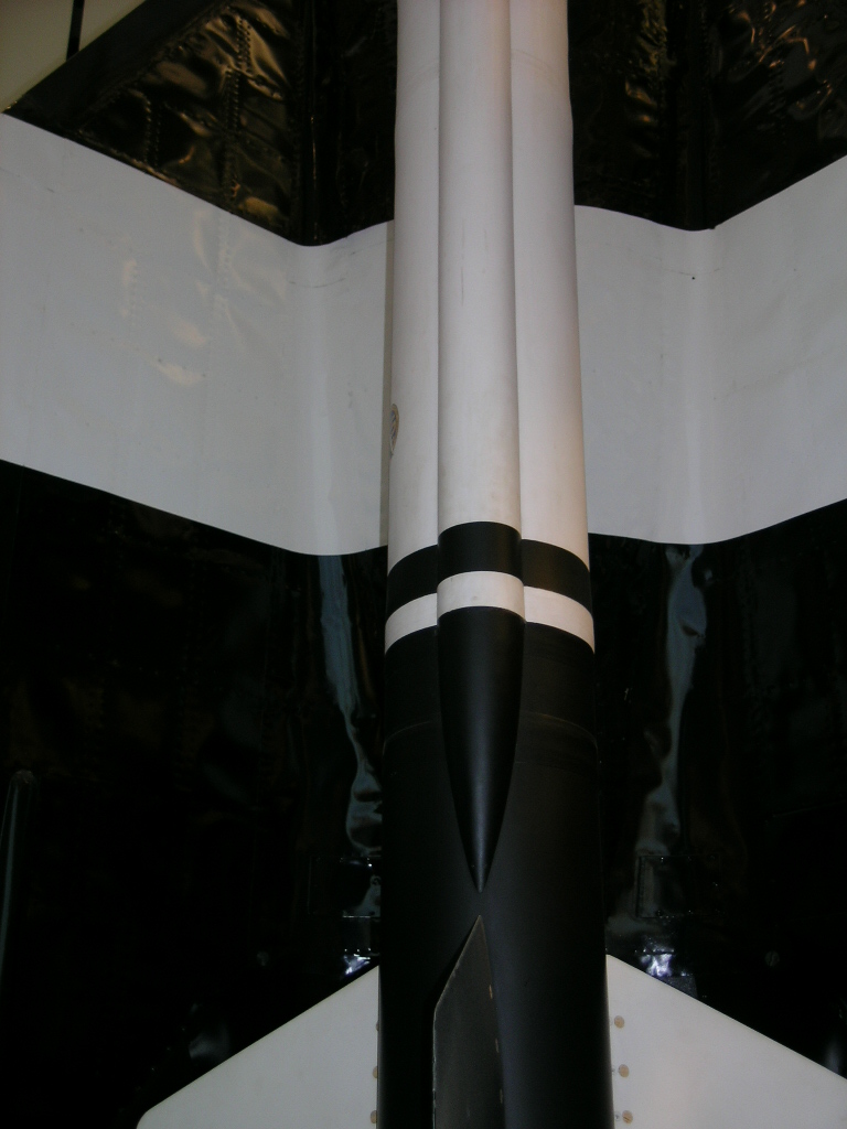
The White Sands Missile Range Museum sent me these great pictures with additional detail on the booster and sustainer. (Click on individual images for the 300dpi scans.)
 02-037-001 02-037-001 |
 02-037-002 02-037-002 |
 02-037-003 02-037-003 |
 02-037-004 02-037-004 |
 02-037-005 02-037-005 |
 02-037-006 02-037-006 |
 02-037-007 02-037-007 |
 02-037-009 02-037-009 |
 02-037-010 02-037-010 |
 02-037-011 02-037-011 |
 02-037-424 02-037-424 |
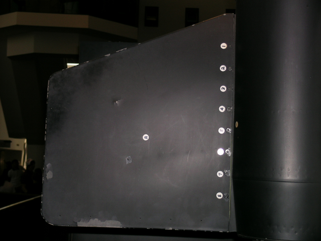
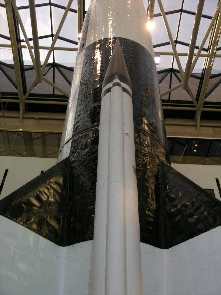
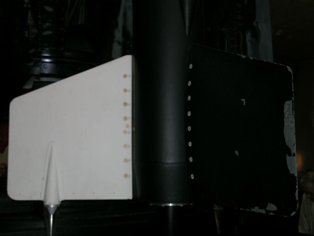
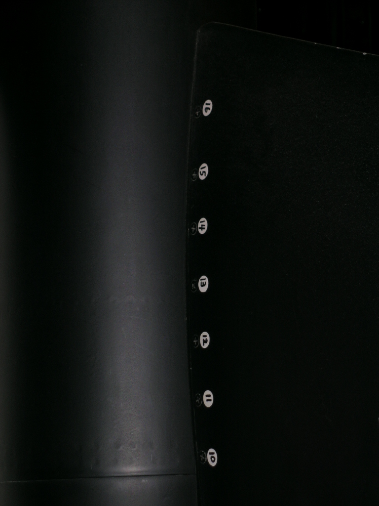
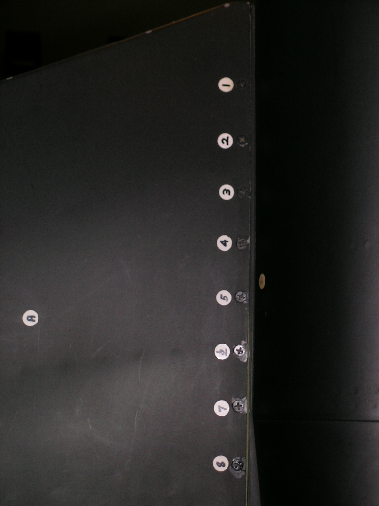
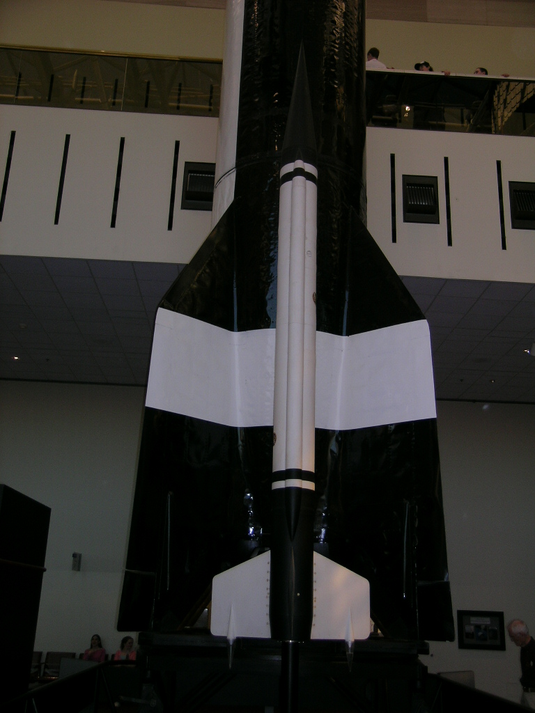
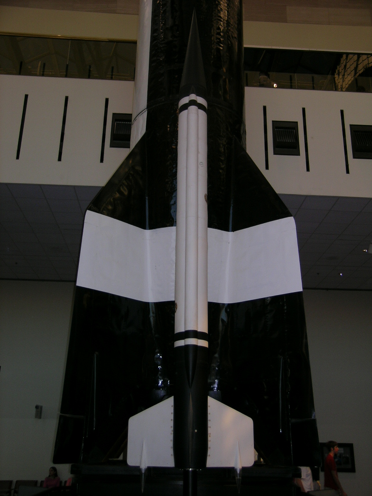
Scott McClusky sent me pictures of the Wac Corporal sustainer on display at the National Air and Space Museum. This was a black and white Bumper Wac (the one which used a converted V-2 as the booster). He was able to get good pictures of the fins for me. Wac 09 has the best view showing the continuous fin curvature.
 Wac 01 Wac 01 |
 Wac 02 Wac 02 |
 Wac 03 Wac 03 |
 Wac 04 Wac 04 |
 Wac 05 Wac 05 |
 Wac 06 Wac 06 |
 Wac 07 Wac 07 |
 Wac 08 Wac 08 |
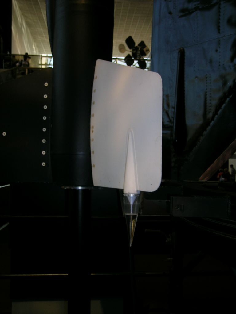 Wac 09 Wac 09 |
 Wac 10 Wac 10 |
 Wac 11 Wac 11 |
 Wac 12 Wac 12 |
I was still concerned about the fin shape because some of the old pictures really look like bevels, but Andy Hobbs set me straight:
"The fins on the Wac Corporal are not beveled, the pictures give a very convincing illusion of bevels but in reality it is a difference in the sheen of the metal fins. You will not find a real Wac Corporal with fins beveled.
This set of photos has fooled alot of people and a number of kit makers including Estes, so the beveling idea just keeps perpetuating itself over and over. Heck, even Q modeling gives out a bevel jig in their kit.
I got this information from Peter Alway and I have also seen the rocket first hand; no bevels."
So that settles it. I will model the full curvature shown so nicely in the Wac 09 picture above.