Sleek
In 2020, Ken Biba was investigating optimal shapes and the trade-offs of rocket design at different speed regimes. Ultimately, this was to optimize high-altitude flights on large motors, but in the mean time there were experiments at 38 amd 54mm minimum-diameter and I decided to use his design to build one of my own.
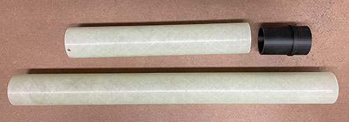
My experience with 3D printing has grown over the years and I decided to make all the parts other than the tube itself this way. There aren't any CNC routed parts in this rocket; it's a fiberglass airframe and the rest 3D printed in Nylon reinforced with carbon fiber.
The Pictures
The Design
Because this rocket spends most of its time at low Mach numbers, the optimal nose cone shape is a power series with exponent 0.5. The length of the rocket is also critical, so I kept it just long enough for an AeroTech RMS-54/2560 case and 12" of recovery space. This will be tight, and I have to squeeze in dual-deployment from a single opening.
The overall drawing is pretty simple.
Construction
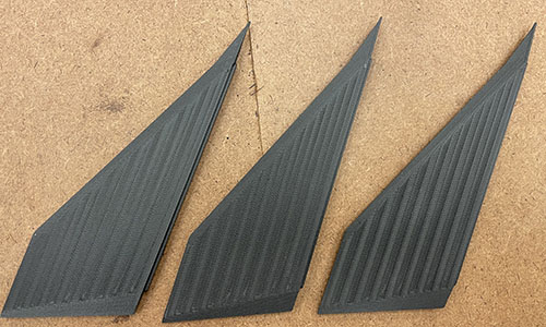
Ken actually designed his as a fin can, but the 3D printer I used can't print a part that large. (The MarkForged MarkTwo prints fantastic quality parts, but has a smallish build volume.) So I decided to print the fins individually. This also gave me the option to orient them horizontally and reinforce them with continuous carbon fiber strands.
Here are the fins just off the printer. They're a bit rough because the surfaces are all angled, so I had some post-processing to do.
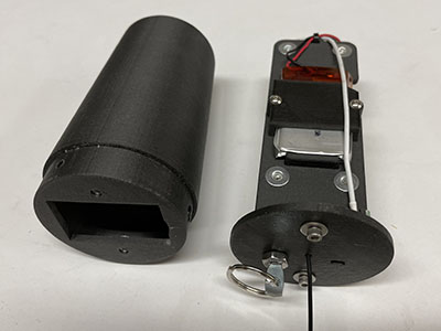
Here's a view of all the 3D printed parts of the airframe, other than the fins. The fins were printed in Nylon with carbon fiber bits incorporated (but not continuous strand reinforcement), called "Onyx" by MarkForged.
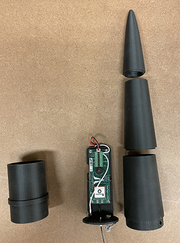
The only coupler doubles as the motor retainer and is bonded into the aft airframe and the forward (recovery) airframe slides onto it.
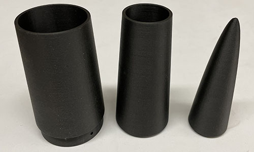
I used the excellent OpenSCAD programs by Bill Kalsow to produce the STL files for the nose, which I had to print in 3 sections.
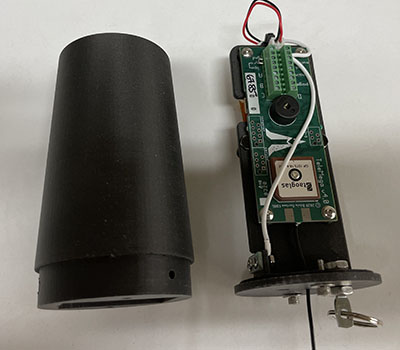
An AltusMetrium TeleMega fits into the nose. I extended the antenna aft into the recovery bay to avoid interference from the carbon fiber in the nose itself.
The coupler was bonded into the aft section of airframe and the three parts of the nose were bonded together. Then the fins needed to be bonded on. I did find a use for the CNC router: to slot the tube to align the fins. The slots don't go all the way through, but tabs printed on the base of fins fit tightly into the routed slots to create good alignment and provide a little more bonding area for these minimum-diameter fins.