Printed Components
It's clear that additive manufacturing (3D printing) is the future of short-run fabrication. However, it's far from clear whether the mechanical properties of typical 3D printed parts are sufficient for high-power rocket construction. This article documents my experiments get some numbers by testing three hypotheses:
- 3D printed parts are weaker than those made of traditional materials.
- Traditional materials produce parts that are stronger than they need to be.
- By optimizing the material, design and printing techniques, we can make printed parts strong enough.
Clearly these hypotheses are somewhat contingent on each other, but I'm testing the first two in parallel because I think both are interesting in themselves. Of course, proving the third is the ultimate goal.
The Tests
The first round of tests includes four different structures to test the absolute strength of ¼" (6mm) plywood centering rings (CRs) and bulkheads and the strength of a typical epoxied assemblies using them. I chose the most common HPR size: 98mm (3.9") body tubes and the CRs are for 54mm MMTs.
| Test 01 | Test 02 | |
 |
 |
|
|
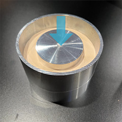
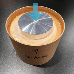
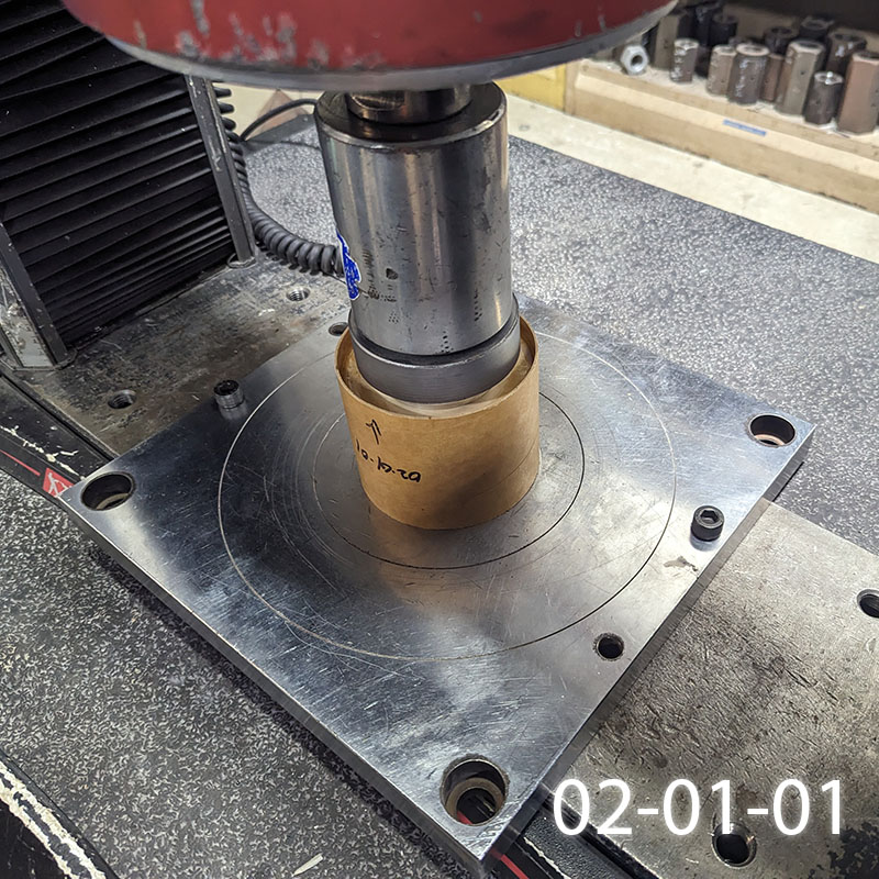
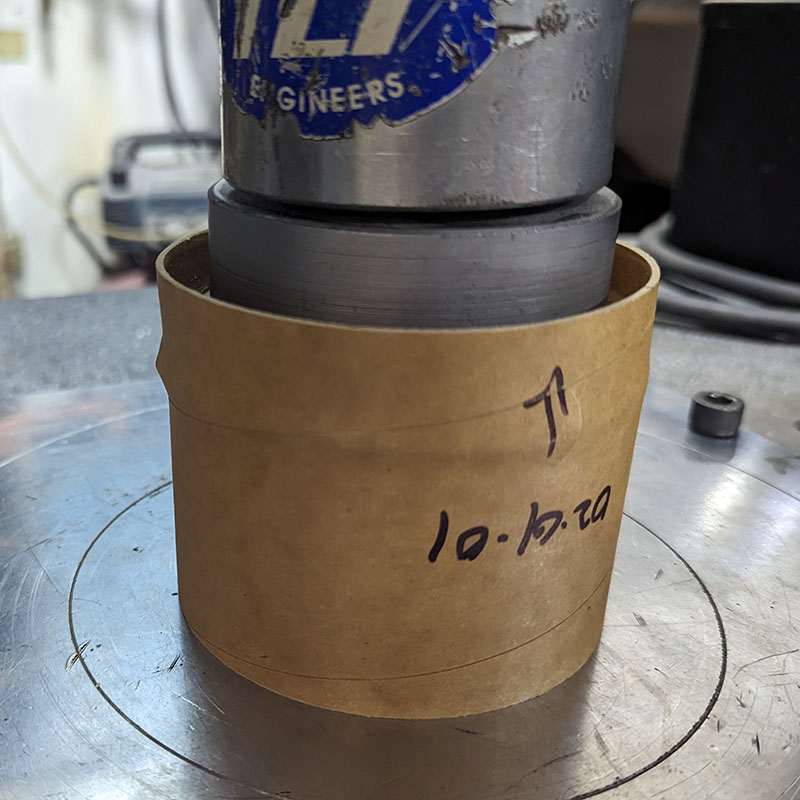
Break CR by pushing down on center. Test the absolute strength of a CR by pushing a lip on the inside against a lip on the outside. |
Break epoxy bond by pushing on center. Test the weakest component of a bonded CR by pushing a lip on the inside of the CR. |
|
| Test 03 | Test 04 | |
 |
 |
|
|
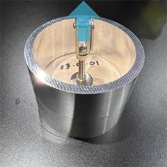
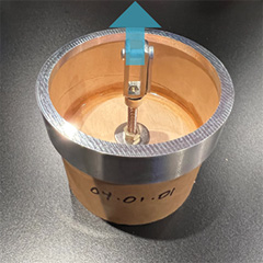
Break bulkhead by pulling up on center. Test the absolute strength of a bulkhead by pulling a ¼" bolt/fender washer through a hole in the center against a lip on the outside. |
Break epoxy bond by pulling on center. Test the weakest component of a bonded bulkhead by pulling a ¼" bolt/fender washer through a hole in the center. |
Tests 01 and 02 simulate motor thrust being transferred to the body tube through the CRs. Tests 03 and 04 simulate parachute opening force where it's tethered to a bulkhead. Note that there are two series for Test 04: without and with and reinforcing coupler ring above the bulkhead.
The baseline parts are ¼" 5-ply "birch" plywood and the body tubes are Giant Leap flexible phenolic. All parts are for standard 3.9" (98mm) ID tubing. Epoxy bonds were AeroPoxy ES6209 with "gloved finger" fillets.
The Samples
The baseline material was ¼" 5-ply "birch" plywood, and the 3D printed samples were various materials and printers. Note that the filament was purchased from the printer manufacturer and the prints were all run with default printer settings.
| Material | Printer | Technology | Series |
| Onyx | Markforged MarkTwo | FFF | 10 |
| Onyx + CF | Markforged MarkTwo | FFF | 11 |
| ABS | Ultimaker S5 | FFF | 20 |
| PETG | Ultimaker S5 | FFF | 21 |
| PLA | Ultimaker S5 | FFF | 22 |
| Tough PLA | Ultimaker S5 | FFF | 23 |
| ABS | BambuLabs X1C | FFF | 30 |
| PAHT-CF | BambuLabs X1C | FFF | 31 |
| PETG-CF | BambuLabs X1C | FFF | 32 |
| PC | BambuLabs X1C | FFF | 33 |
| PLA | BambuLabs X1C | FFF | 34 |
| Tough 2000 | FormLabs Form3 | resin | 40 |
| PA12 | HP Multi-Jet Fusion | FDM | 50 |
Note that all of these are FFF printers except for the Form3 which is resin and the HP MJF which is FDM. The HP MJF parts were purchased through Shapeways; the other parts were from printers I own.
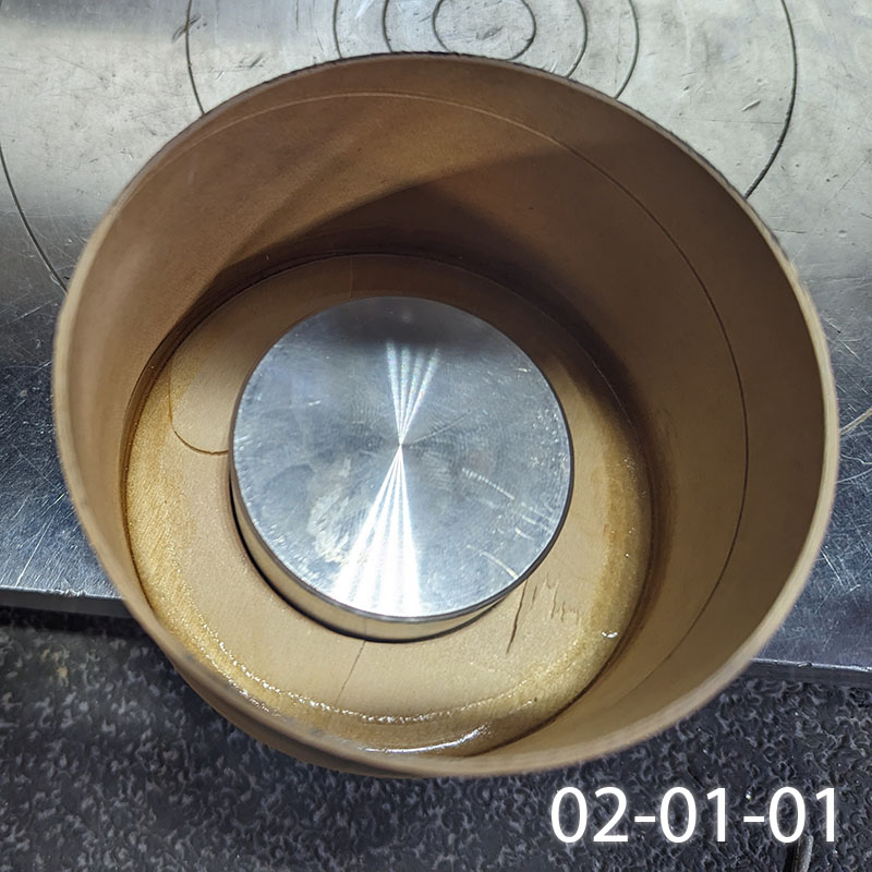
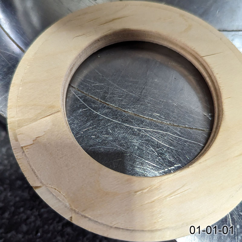
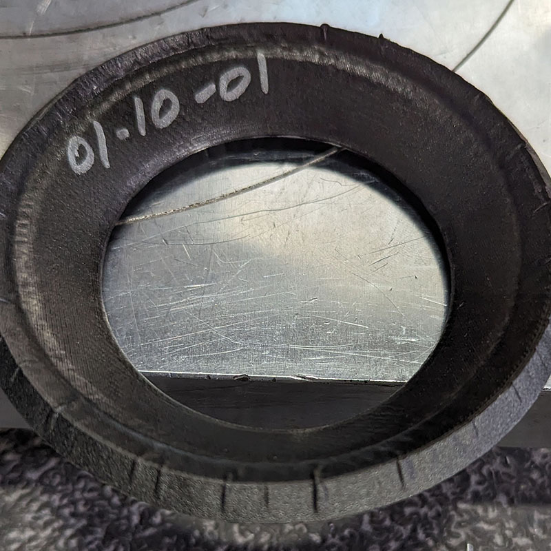
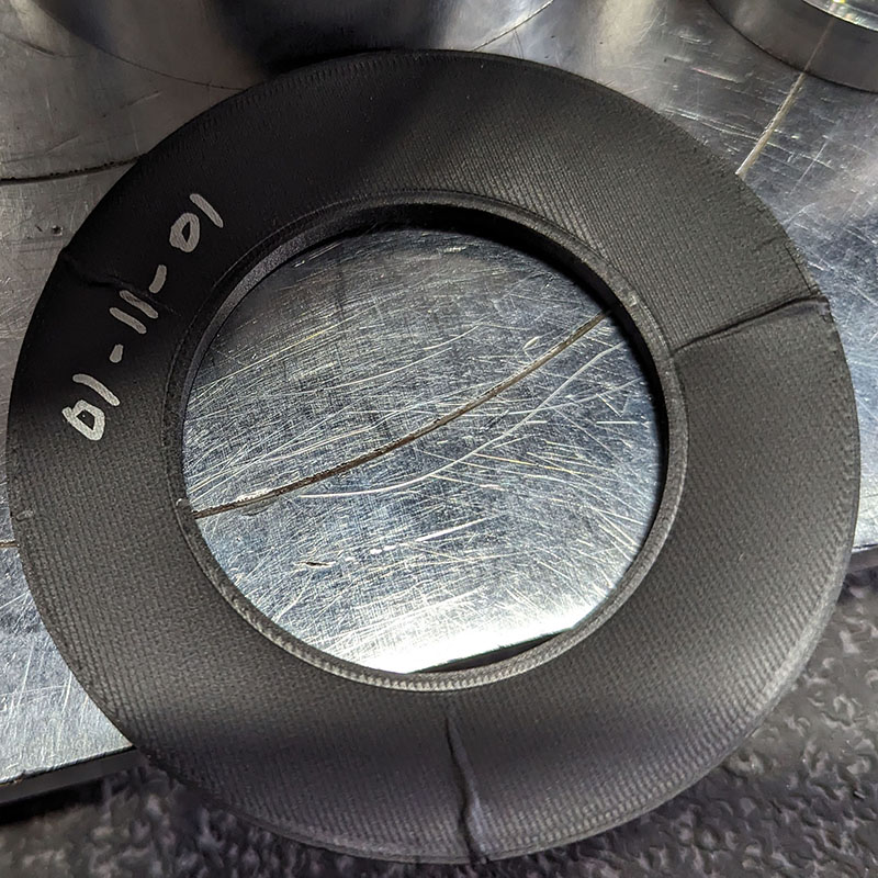
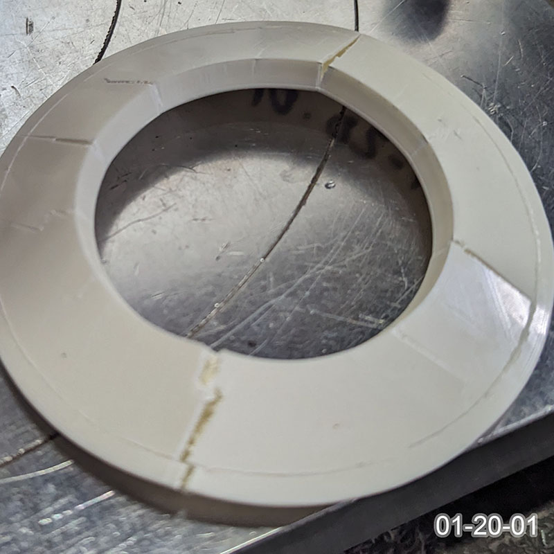
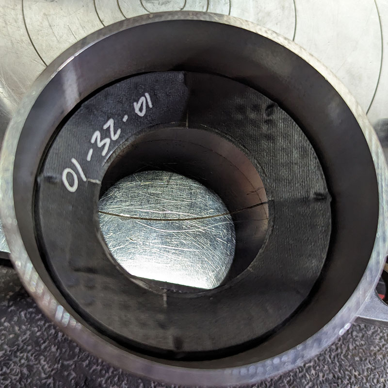
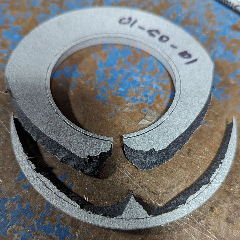
Three samples of each series were tested in order to guage the variance in material and fabrication. (PLA was not used for CRs because of its low heat tolerance.) Each sample is identified with three numbers, for example "01-20-03" is:
- test 01 (CR absolute strength)
- series 20 (ABS on Ultimaker S5)
- sample 03 (3 / 3)
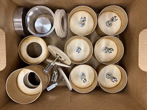
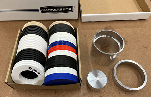
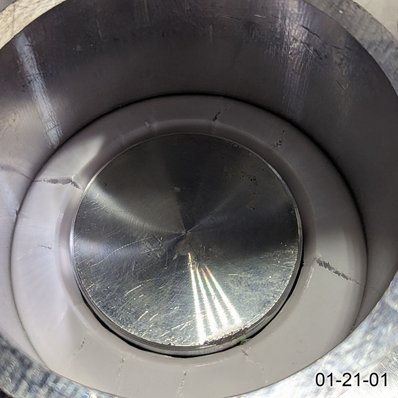
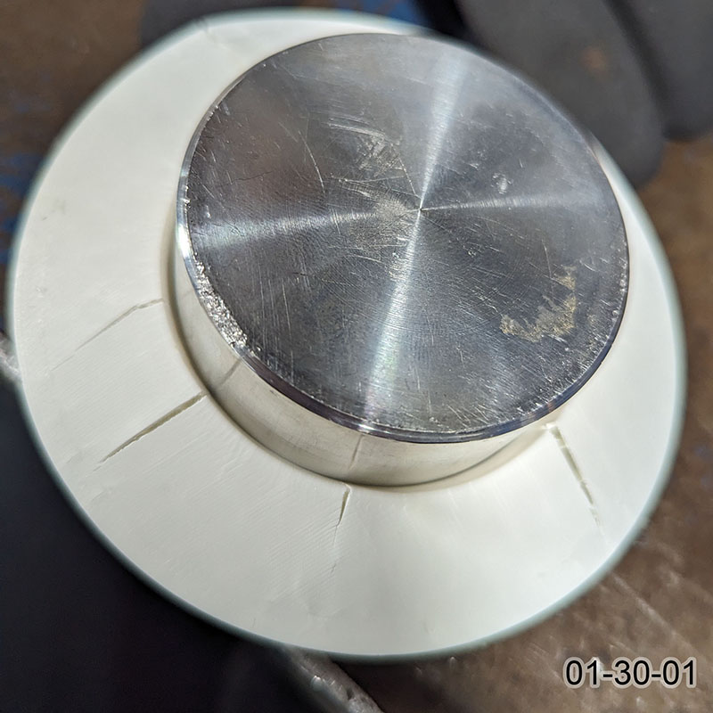
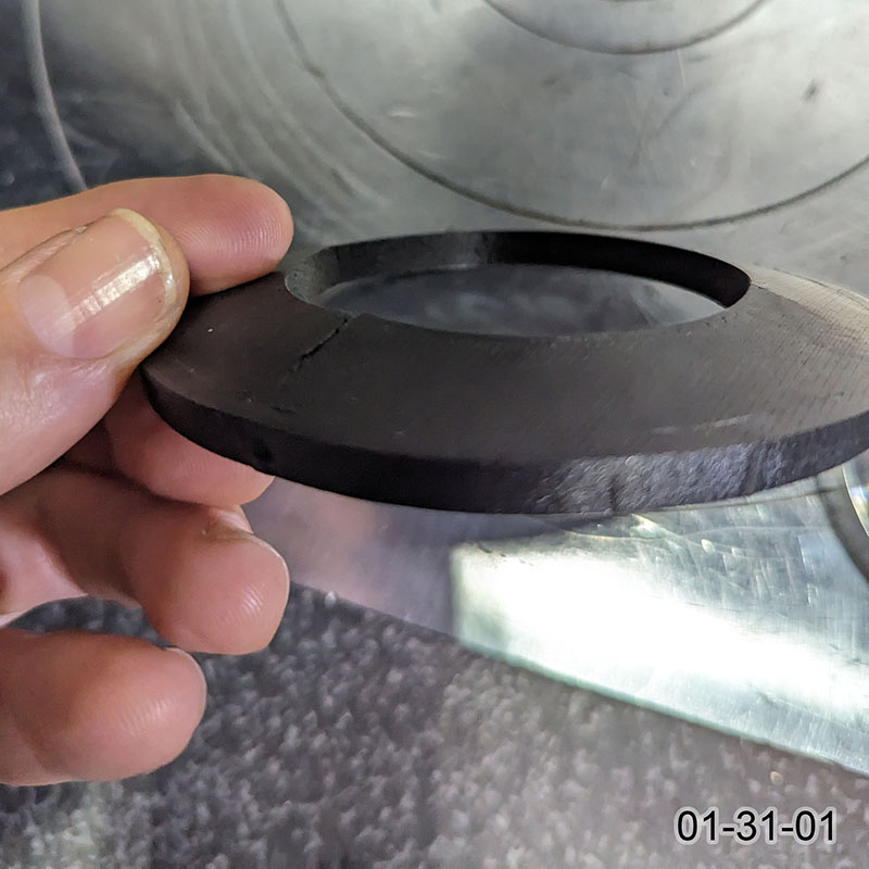
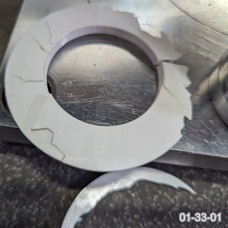
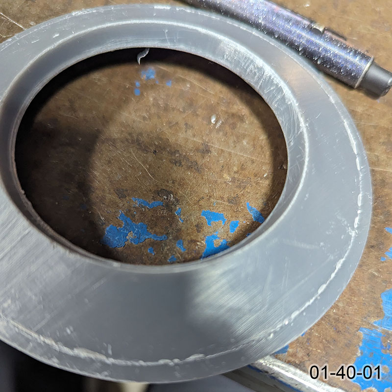
Here are some of the samples for tests 01 and 03 and the aluminum fixtures used for testing them.
Hypothesis 1
3D printed parts are weaker than those made of traditional materials.
This turned out to be very much of a mixed bag. Some 3D printed parts (even in plastic) were much stronger than plywood, while others were much weaker. This proves a modified form of this hypothesis:
Parts printed on consumer-grade printers with default settings are much weaker than plywood.
I want to stress the "with default settings" here. These numbers should not be read as what these machines are capable of, but only what they produce by default. You can compare filaments on the same machine, but not between machines.
| Series | Material | Machine | Force (lbf) |
| 01-01 | plywood | ShopBot | 771 |
| 01-10 | Onyx | MarkTwo | 433 |
| 01-11 | Onyx+CF | MarkTwo | 1327 |
| 01-20 | ABS | S5 | 406 |
| 01-21 | PETG | S5 | 497 |
| 01-30 | ABS | X1C | 260 |
| 01-31 | PAHT-CF | X1C | 393 |
| 01-32 | PETG-CF | X1C | 214 |
| 01-33 | PC | X1C | 429 |
| 01-40 | Tough 2000 | Form3 | 1294 |
| 01-50 | PA12 | HP MJF | 594 |
Of note: parts printed with continuous CF reinforcement on a MarkForged MarkTwo or using Tough 2000 resin on a Form3 are almost twice as strong as the equivalent plywood parts. All other samples were significantly weaker.
I want to stress the "with default settings" again. You can compare filaments on the same machine, but not between machines.
Hypothesis 2
Traditional materials produce parts that are stronger than they need to be.
The first of results I got was for all four tests with plywood and phenolic, which brought this hypothesis into doubt. The breaking force of the plywood centering rings and bulkheads was not higher than the breaking force of the bonded assemblies. Below you can see that the parts and assemblies broke at roughly the same force:
| Component (lbf) | Assembly (lbf) | |
| CR | 771 | 799 |
| bulkhead | 616 | 611 |
Note that in the assemblies, the glue bond did not fail. Instead the ring crushed and the tube buckled. So the epoxy bond is also not the weakest link; it seems that all parts are roughly equally balanced for strength.
The conclusion I'm taking from this test is that comparing the strength of 3D printed CRs to plywood CRs is a reasonable proxy for "strong enough" (not over-building relative to the other materials and techniques).
Hypothesis 3
By optimizing the material, design and printing techniques, we can make printed parts strong enough.
This is the experimental part of this article: What printer settings and geometry will increase the strength of a consumer-grade printed part to that of plywood? All samples in this section are printed in ABS on the Bambu X1C so they are directly comparable.
Print Settings
The most obvious settings are related to infill (the inner volume filled with a lattice rather than solid plastic like the top, bottom and sides). The two main options here are density (what percentage is solid) and pattern (the shape of the lattice). Following conventional wisdom, I had been using 50% and gyroid as a matter of course. Now it was time to test those assumptions.
The charts below all have the same range (800 lbf) and the dotted line is the plywood CR strength (771 lbf) that we're trying to reach.
What really surprised me is how important the number of "wall loops" is. This is the thickness of the outer sides of the part, and clearly it has a big impact on the shear strength of a centering ring. We're getting there: ABS with 50% gyroid and 8 wall loops broke at an average of 692 lbf, 90% as strong as plywood of the aame shape. See the raw data at the bottom. (Beyond that, we're just making a pretty much solid part, especially for a CR.)
Due to the importance of wall loops, I tried experimenting with the number of top/bottom layers. This had an effect, but not nearly as marked as you can see above.
ABS, 50% infill, gyroid pattern, 8 wall loops, 8 top/bottom layers
We have our basic print settings!
Part Geometry
Of course, being 3D-printed, we can play with the shape of the part a lot more easily than with a part cut from a sheet (plywood, G10, phenolic, etc.). I thought that instead of just making the simple parts thicker, they could be made partly thicker and use a truss structure to take advantage of that thickness without adding too much weight.
In order to make it easy to experiment, I programmed a ribbed CR in OpenSCAD. This allows me to define input parameters to adjust the size, thickness and number of ribs. It also means that the CR will "scale up" automatically based on the OD. You can download the file here: CR v1.scad. If you haven't experimented with OpenSCAD, I hightly recommend giving it a try (it's free).

I started with a 6mm base (the same as the reference ring thickness). The height of the ribs has a dramatic effect on strength. Note that we've immediately left the reference strength behind!
The next test was for the number of ribs. I had started with 12, for no special reason, so I thought it would be interesting to vary that. This has a much less pronounced effect, and it appears 12 ribs, or maybe 15, is a good choice.
The next test was for thinning the base. I had started with 6mm, to match the thickness of the reference ring, with the ribs adding to that making higher total heights. The ribs add a lot of strength, which seems to swamp the effect of the base thickness. Since the overall height stayed the same, the based was thinner but the ribs were taller. Down to 4mm, it appears that the ribs provide more strength than the base does.
In all the above charts, the bluish bar is the same (12mm overall, 6mm base, 12 ribs). The charts all have the same scale so can be directly compared.
Once I had a feeling for how much the different factors affected the strength, I thought I would try to optimize a bit. After all, the lightest of these samples (07-22) at 32g is 60% heavier. Also, probably of lesser importance, at 9mm is 50% thicker. And it's 66% stronger than the plywood.
This once again shows how much strength the ribs add. We really can't get the CR to the same thickness as plywood and maintain strength. However, the 10mm overall (4mm base + 6mm ribs) is still 67% stronger than plywood and only about 1½ times the weight (29 vs 20 grams). You could also choose the 4mm ribs for basically the same strength and only 1¼ the weight (25 grams).
4mm base, 12 ribs 6mm high (10mm overall)
To bring things full-circle, I ran a final test with the ABS centering rings bonded into phenolic tubes. This demonstrated that the rings held up, in fact better than the plywood rings, as they would be used.
Note that the rings are significantly stronger with the ribs to the aft, so I would definitely also recommend using this orientation. I believe this is due to the way the force is dissipated in this shape.
The OpenSCAD file uses these dimensions as a starting point for your own projects. Enjoy!
Raw Data
Here is the raw data from the testing lab. Note that I broke three samples of each unique combination and the values displayed above are the average of those three samples. (Force is in lbf and displacement is in inches.)
Test 01
Each test result: Test 01 spreadsheet.
Test 02
This test was testing the centering rings bonded into phenolic tubing. I tested the both baseline plywood CRs and the final configuration ABS CRs. (See Hypothesis 2 for more info.) Each test result: Test 02 spreadsheet.
Test 05
These tests were for the exploration of Hypothesis 3, print settings. Each test result: Test 05 spreadsheet.
Test 07
These tests were for the exploration of Hypothesis 3, part geometry. Each test result: Test 07 spreadsheet.