H.P.R. Kit Building
This information was originally published on the Rocketry Online How-To Classroom Forum. I have published it here as well since ROL is now defunct.
Lesson 0: Introduction
This How-To Classroom forum series covers building a high-power rocket kit, capable of flights on H or larger motors suitable for level 1 certification or general sport flying. We're going to concentrate on good basic construction techniques for high-power rockets.
Let's start with a kit. Kits from good manufacturers provide a well-thought out and tested rocket plan, most of the materials to build it and good instructions. The best kind of kit for a first high-power rocket, and particularly a level one certification rocket, is a simple one. Choose a kit with three or four fins on the aft end and no fins forward. A "three fins and a nose cone" (3FNC) rocket is ideal.
 Good first kits are available from many manufacturers, notably Public Missiles,
Ltd. and Loc/Precision.
The kit we will build in this series is the
Yank Enterprises (now part of Loc/Precision)
4" IQSY Tomahawk (with 54mm motor mount tube).
The kit you choose shouldn't be critical as we're going to concentrate on technique,
and you should choose a kit which appeals to you.
Good first kits are available from many manufacturers, notably Public Missiles,
Ltd. and Loc/Precision.
The kit we will build in this series is the
Yank Enterprises (now part of Loc/Precision)
4" IQSY Tomahawk (with 54mm motor mount tube).
The kit you choose shouldn't be critical as we're going to concentrate on technique,
and you should choose a kit which appeals to you.
Tools and Supplies
Many of the tools and supplies used in high-power rocketry are the same as those used in model rocketry (and modeling in general).
- X-Acto® knife and blades
- razor saw
- sandpaper in assorted grits (at least 60, 100 and 220)
- drill and bits
- screwdrivers
- masking tape
- ruler with a metal edge
- pencils and pens
Some other useful supplies for high-power rocket building:
- thread locker (Loc-Tite® or similar)
- palm sander
- Dremel® tool
- pliers and wrenches
- small drafting squares
- aluminum angle (as long as your longest tube)
- rubbing alcohol
Note that we are ignoring painting supplies for now and will cover painting supplies and techniques in the last installment of this series. (We will paint the rocket using spray cans for simplicity.)
Epoxy
 Bonding deserves a special discussion. Most high-power rocket kits are
bonded with epoxy rather than white glue (aliphatic resin). Epoxy is a
generic term which refers to a certain type of two-part adhesives. One part
is called the "resin" and one the "hardener." You mix the two together and
within a certain period of time, which varies by the type of epoxy, the
mixture solidifies and creates a very strong bond.
Bonding deserves a special discussion. Most high-power rocket kits are
bonded with epoxy rather than white glue (aliphatic resin). Epoxy is a
generic term which refers to a certain type of two-part adhesives. One part
is called the "resin" and one the "hardener." You mix the two together and
within a certain period of time, which varies by the type of epoxy, the
mixture solidifies and creates a very strong bond.
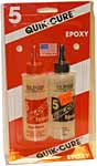
The epoxy most people start out with is "hobby shop" epoxy, often made by Bob Smith Enterprises. This epoxy is mixed with a 1:1 ratio (the same amount of resin and hardener) and comes in several versions. The most commonly used versions are 5 minute and 30 minute. The number of minutes refers to the "pot life" and is amount of time until the "gel" stage. When the epoxy gels it is no longer runny, but is still not "cured." Curing is the process of hardening and full cure can be an hour to days (depending on the epoxy type). Note that the times are very approximate and depend on the amount you mix and the ambient temperature. The 5 minute epoxy sets faster which allows you to work more quickly, but may not produce quite as strong a bond and will not penetrate porous surfaces as fully.
There are many epoxies available. Many people like to use the "epoxy systems" such as West System, FibreGlast and Raka. These systems all offer a much broader range of products, but involve a higher initial outlay. See the articles on epoxy in the INFOcentral CONSTRUCTION area.
For mixing epoxy, you need small sticks such as craft (Popsicle®) sticks. For larger amounts, it is also useful to have disposable cups, such as the Solo® plastic cups. Don't use Styrofoam or paper cups though. For mixing smaller amounts, a pad of 2" square Post-It notes works well. You should also wear latex or nitrile gloves when working with epoxy. Skin clean-up is best done with citrus hand cleaners like GoJo® or Fast Orange®. Tool and drip clean-up can be done with rubbing alcohol (70% isopropyl is fine).
Check Out Your Kit
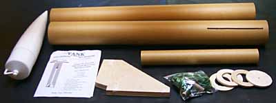
![]() Once you receive your chosen kit, open the box carefully, take out all the
parts and find the instructions. Lay out all the parts on a safe surface
and read through the instructions. Try to make sure that you have all the
parts and understand how the rocket will go together. If you understand how
the pieces fit together, you will be much less likely to make a mistake.
Once you receive your chosen kit, open the box carefully, take out all the
parts and find the instructions. Lay out all the parts on a safe surface
and read through the instructions. Try to make sure that you have all the
parts and understand how the rocket will go together. If you understand how
the pieces fit together, you will be much less likely to make a mistake.
Make sure you have all the tools and supplies needed to build your kit. Sometimes the instructions come with a list of things you'll need and other times you'll have to figure this out from the instructions. Having everything ready before you start will make building the kit much more fun and improve your results.
The quality of instructions varies quite a bit between different manufacturers. However, the major manufacturers all provide reasonable instructions. They do expect you to know certain basic high-power construction techniques, which is where this how-to series comes in.
Lesson 1: The Motor Mount
In this lesson, we're going to build up the motor mount and install it into the booster body tube section. See lesson 0 for the introduction and preparations.
The first thing the instructions for my Tomahawk say to do is build the motor mount tube (MMT) and centering rings (CRs). Right off the bat, there are a few things to think about.
Motor Retention
The instructions don't mention motor retention until the end of the construction phase, but you need to plan for motor retention before building the motor mount. If you're planning to use AeroTech reloadable motors, you have many choices. I like the Aero Pack retainers, but many other styles are possible. See also the Motor Retention article in INFOcentral.
I have chosen to use the Aero Pack retainers because they are the slickest thing going. However they are a bit pricey. To use these retainers, the MMT must stick out 9/16" from the aft centering ring (for the 54mm size). This means we have to adjust the position of the centering rings a bit from the instructions.
If you choose to use other retention systems or a home-made system (Kaplow clips), you should install the T-nuts into the aft centering ring at this time.
Interior Fillets
I like to use good interior fin fillets in rockets with through-the-wall fins. The Tomahawk instructions (like most kits) tell you to bond all the centering rings to the motor mount tube at the same time. I like to modify this by leaving the aft one loose until after the fins are mounted.
My kit already had three CRs, but if yours has only two, I suggest you add a third one for additional support and to make alignment easier. If your MMT is short and you have plenty of space in the booster, you might also want to use a longer MMT to provide more support for long motors.
When we bond the motor mount into the booster airframe, we will bond only the two forward CRs. This way, we can add fillets inside the airframe and make a really solid fin bond. This also allows the forward and aft CRs to tightly match the fin tabs making a solid structure.
Bonding the CRs
Measure the aft edge position of the CRs on the MMT and mark them with pencil. Another key tip that is usually left out of instructions is that you need to scuff up and clean phenolic surfaces before bonding. Once you have the marks drawn, sand the tube from the aft end up past the center CR location with 60 grit sand paper. Also sand the forward end of the MMT (where the forward CR will bond). Wipe off the MMT with alcohol.
 It's important to get the center CR on perpendicular to the axis of the
MMT. This allows all four fins to butt against this CR and still be
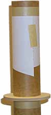
aligned. Draw a line around the MMT at the mark. A neat trick to make the
line even along the MMT is to take a piece of paper and wrap it around the
tube. When you get one edge of the paper to touch the mark and wrap back
around itself in a straight line, you have a good edge. Draw a line here.
It's important to get the center CR on perpendicular to the axis of the
MMT. This allows all four fins to butt against this CR and still be
aligned. Draw a line around the MMT at the mark. A neat trick to make the
line even along the MMT is to take a piece of paper and wrap it around the
tube. When you get one edge of the paper to touch the mark and wrap back
around itself in a straight line, you have a good edge. Draw a line here.
 To support the CRs while the epoxy is curing, I like to wrap a band of
masking tape around the tube. Put down a wrap (or more if the CRs are
loose) with one edge of the tape at the center CR line. Then slide the CR
down onto the tape and proceed to the forward CR. Now you can apply the
epoxy without worrying about the CR moving. Only apply the fillet on the
side opposite the tape. Once the epoxy gels, you can take off the tape and
apply a fillet to the other side (for the forward CR only this time).
To support the CRs while the epoxy is curing, I like to wrap a band of
masking tape around the tube. Put down a wrap (or more if the CRs are
loose) with one edge of the tape at the center CR line. Then slide the CR
down onto the tape and proceed to the forward CR. Now you can apply the
epoxy without worrying about the CR moving. Only apply the fillet on the
side opposite the tape. Once the epoxy gels, you can take off the tape and
apply a fillet to the other side (for the forward CR only this time).
Note that at this time, we will only apply a fillet to the forward end of the center CR. Apply fillets to both sides of the forward CR and don't bond the aft CR at all.
If you are using an epoxy system where you have to add fillers, paint some unthickened epoxy on the wood parts before adding the filler. For example, I use West System products, so I mix up an ounce of 105/205 and stir it thoroughly. Then paint a little on the CRs at the joint with the tube. (Try not to get it on the outside of the CRs.) Then, thicken the epoxy with your chosen filler (I use 404 for most bonding) and apply your fillet as usual.
If you are using hobby shop epoxy, squeeze out an equal blob from both bottles onto your pad of Post-It notes and mix thoroughly. Then apply the epoxy to the joint and make an even fillet. The Post-It notes are nice because you can just throw away the top one each time you mix epoxy and have a fresh surface.
Install the Eye Bolt
My kit included eye bolts for the recovery system. Install the MMT eye bolt per the kit instructions. However, I suggest you use thread locker (such as LocTite®) to make sure the nuts don't come off. (My Tomahawk kit was missing one of the two nuts for each of the eye bolts, which is why it's a good idea to check your kit contents before you start building.)
My instructions said to epoxy the parachute bridle to itself through the eye bolt. This is messy and too permanent for Nylon (which wears out over time). It's better to use a quick link here and sew or tie a loop in the Nylon strap.
One key tip: When you install the eye bolt, make sure it won't get in the way when you try to install the motor mount into the airframe. Also turn it so that you will have an easy time getting the quick link through the eye bolt when you rig the recovery system. If you have the space, align the eyebolt so that the hole is at right angles to the inside of the airframe.
Install the Motor Mount
Once the fillets on the two CRs have cured, it's time to install the motor mount into the booster airframe. Sand the inside of the booster airframe with 60 grit sandpaper around the fin slots and where the CRs will bond. (Don't sand the all the way up to the very forward end of the tube.) Wipe off the inside with alcohol. These are important joints so take time and make sure they are right.
Mix up epoxy for bonding the two CRs into the airframe. Often, it is almost impossible to get epoxy on the forward edge of the center CR. Slide the motor mount into the airframe until the center CR is just below the top of the fin slots. Drip/push as much epoxy as you can into the top of the fin slots and try to get it to run around the body tube against the forward end of the center CR. Then push the MMT into the airframe until the aft edge of the center CR is at the top of the fin slots.
If the airframe is slotted correctly and you got the CR on properly, it should line up exactly at all fin slots. Double-check your work at the aft end of the MMT. Lay a ruler across the aft end of the airframe tube; it should touch the mark you made on the MMT for the aft CR.
Since we left the aft CR loose, but will use it for alignment, we need to be careful not to bond it in place when things get messy. Make sure the aft end of the MMT and body tube are free of epoxy and your hands are clean. (Wipe the tubes clean with alcohol if necessary and take off your gloves.) Now carefully slide the aft CR onto the MMT until it just barely touches the aft end airframe. Don't slide the CR all the way inside the airframe because you will need to pull it out again. This will help keep the MMT aligned properly inside the airframe while the epoxy cures.
Now bond the forward CR to the airframe. From the forward end of the airframe, apply some epoxy with a long stick to the outside edge of the forward CR. Get a good fillet here and smooth it with your finger. Be careful not to drip epoxy on the inside of the airframe and if you do, clean it off with alcohol. Be very careful not to get epoxy inside the MMT or you will be very sorry when you try to install a motor!
Let the booster section sit until the epoxy is fully cured. You can set the airframe on a roll of tape with the MMT through the hole in the center if you think the weight of the airframe might change the position of the motor mount while curing.
Lesson 2: Installing Fins
In this lesson, we're going to install the fins and finish the motor mount. See lesson 1 on building and installing the motor mount itself.
Shaping Fins
 My Tomahawk kit came with wooden fins, but if you are building a PML kit,
it will come with G10 (fiberglass) fins. Either way, you will most likely
want to dress the visible edges of the fins in some way. My instructions
said to do this after the fins are mounted, but I find it easier to do when
the fins are still loose.
My Tomahawk kit came with wooden fins, but if you are building a PML kit,
it will come with G10 (fiberglass) fins. Either way, you will most likely
want to dress the visible edges of the fins in some way. My instructions
said to do this after the fins are mounted, but I find it easier to do when
the fins are still loose.
If you are concerned with performance, you will want to get as much of an airfoil shape on the fins as possible. This generally involves a rounded leading edge and tapered trailing edge. For this kit, I chose to bevel (taper) all three exposed edges of each fin. Be sure not to round or bevel the root edge (or the tab ends)!
Safety note: Sanding G10 (or any fiberglass) produces very dangerous fine particles. Use a good respirator and sand outside (or in a well-ventilated area) to reduce your exposure as much as possible.
Clean Up the Fin Slots
Now that you have the MMT installed, test fit your fins into the slots. Clean up the slots as necessary and make sure they are long enough. For my Tomahawk kit, I had to even out the fin slots and make them slightly longer to accommodate the fins.
It's a good idea to check that the fin slots are parallel to the axis of the airframe as well. Lay your aluminum angle along the length of the body tube next to each fin slot and verify that they are straight and in line. If they are not, you can adjust them a bit by widening where necessary.
The straighter your fins are, the better your flight will look and the more altitude you will get. Very crooked fins can even result in a shred, although this will only happen with the more powerful motors.
Now is also a good time to sand the outside of the body tube around the fin slots. This will help the external fillets bond properly. We will mount the fins in the next step, but it's easier to sand the slots now than after the fins are mounted.
Install the Fins
In order to help align the fins, draw a good mark at the aft end of the airframe at the center of each fin slot. If your rocket has three fins, draw another mark exactly half way between each pair of fins.
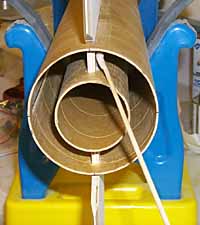
Remove the aft CR and make sure the MMT and inside of the fan can are clean and well sanded. Place the body tube in a cradle so that it is securely supported in a horizontal position. (Robart or similar model airplane stands work well for this purpose.) Turn the tube so that one fin slot is at the very top and position the stand so that the aft end of the rocket is facing out toward you.
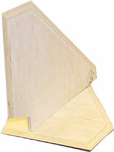
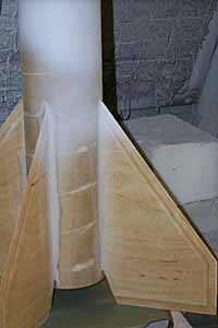
 Take your first fin and put a nice bead of epoxy along the root edge and
the forward edge of the fin tab (where it will meet the center CR). If you
are using an epoxy system, it is a good idea to paint the bottom of wooden
fins with some unthickened epoxy first. In the picture on the left, you can
see one of my Tomahawk fins with unthickened epoxy along the edges and a
thickened epoxy bead along the root.
Take your first fin and put a nice bead of epoxy along the root edge and
the forward edge of the fin tab (where it will meet the center CR). If you
are using an epoxy system, it is a good idea to paint the bottom of wooden
fins with some unthickened epoxy first. In the picture on the left, you can
see one of my Tomahawk fins with unthickened epoxy along the edges and a
thickened epoxy bead along the root.
Slide the fin into the fin slot and make sure it seats on the MMT all along its length. Visually sight along the rocket from the aft end and verify that the fin is straight up (straight out from the tube).
 To make a good joint to the MMT, use a stick to put more epoxy along the
root edge and make as good a fillet as you can along both sides of the root
edge. This is the most important epoxy bond in your rocket so be sure you
make it a good one.
To make a good joint to the MMT, use a stick to put more epoxy along the
root edge and make as good a fillet as you can along both sides of the root
edge. This is the most important epoxy bond in your rocket so be sure you
make it a good one.
Clean up the aft end of the body tube and MMT with alcohol and re-install the aft CR while the first fin bonds. (This will keep the body tube and MMT aligned while the fin bond cures.)
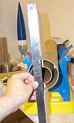 To make sure your fin is properly aligned, lay a long ruler along the aft
end of the rocket, lining up the fin with the marks on the aft end of your
body tube. Use a long piece of tape to hold the fin in position while it
cures.
To make sure your fin is properly aligned, lay a long ruler along the aft
end of the rocket, lining up the fin with the marks on the aft end of your
body tube. Use a long piece of tape to hold the fin in position while it
cures.
Once the fin has cured (or at least reached the gel stage), remove the aft CR and rotate the rocket so another fin slot is at the top. Do all your fins, but don't rush this part or you may get crooked fins. Clean up the aft end of the rocket with alcohol and replace the aft CR after each bond so that your MMT stays in proper alignment with the body tube.
Once the first fin is pointing down, you can also make the fillet inside
the body tube on each side of the fin. When you are done, each fin will
have a good fillet at the MMT and another one at the inside of the body
tube. Make sure that epoxy doesn't run down the fin through any gaps
between the slots and the fins. Use tape if necessary to seal the gaps.
Install the Aft CR
Once all fins are bonded and all internal fillets are done, you can bond on the aft CR. Mix up some epoxy and paint the aft ends of the fin tabs, the outside of the MMT and the inside of the body tube. Slide on the aft CR until it touches the aft end of the fins. Wipe off any excess epoxy with alcohol and let the fin unit cure fully. Now your rocket is really taking shape!
Lesson 3: Completing Construction
In this lesson, we're going to complete the construction of our kit.
Aft End
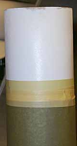
 Finish off the aft end of your rocket by painting the aft centering ring
with thin epoxy. If you are using hobby shop epoxy, the thin stuff is
often sold as "finishing epoxy." If you are using an epoxy system, use the
epoxy unthickened.
Finish off the aft end of your rocket by painting the aft centering ring
with thin epoxy. If you are using hobby shop epoxy, the thin stuff is
often sold as "finishing epoxy." If you are using an epoxy system, use the
epoxy unthickened.
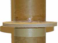
Note how I taped off the aft end of the motor mount tube. This keeps epoxy from it and allows a good bond for the motor retainer later. (I like to install the motor retainers after painting so that they don't need to be masked off.)
The aft CR on my Tomahawk was recessed into the body tube. So I also added a fillet around the edge of the CR to seal it up. If your aft CR is flush with the aft end of the body tube (the more common configuration), fill any gap between the edge of the CR and the BT with thickened epoxy. It's important to have a smooth and hard surface back here as soot from the motor will tend to collect and you want it to be easy to wipe off.
Once the epoxy has cured, sand the aft CR smooth. If you used a fillet, sand it to a smooth transition. If not, sand out any difference between the aft CR and the end of the BT.
Fin Fillets
The final fillets on the fins are the exterior fillets. For the internal fillets, strength is all that's important. For the external ones, looks also count. It's important to end up with a smooth even transition between the fin and the body tube. Not only does this look better when the rocket is painted, but it also produces less drag.
There are several ways to do fillets. Some people like to use thin epoxy and pour the fillets. To do this, use clay to make dams at both ends of the fin and turn the body tube so that the fin and body tube make a valley into which you can pour the epoxy. Fill up the valley between the dams with epoxy and let cure. Once the epoxy has cured, remove the clay dams and sand the fillet to shape.
I prefer to use thickened epoxy to make my fillets. If you thicken the epoxy with a light weight, sandable filler (such as micro balloons), it will be easy to sand the perfect radius. To do this, you need to thicken the epoxy to the point where it doesn't run, sometimes called a peanut butter consistency. Turn the BT so that one fin points straight up and use the mixing stick to pack epoxy into the valleys on either side of a fin. Then drag a gloved finger along the valleys to smooth out the fillet and remove the excess epoxy. Don't worry about getting it perfect now--sanding will make it perfect later.
Once you decide how you are going to make your fillets, it's time to do it. If your model has wooden fins, now is a good time to fill them as well. To fill plywood fins, paint thin epoxy on each one just before making the fillets for it. This way, the thin epoxy will soak into the plywood and provides an extra strong fillet bond. (Remember how we pre-painted the wood for the interior fillets?)
Once the epoxy has cured, sand a smooth radius on all your fillets. If you have wooden fins, lightly sand them to remove the epoxy bumps. Don't go finer than 100 grit at this stage; just remove any visible irregularities.
Electronics Bay
Read through the rest of your kit instructions again and see what is left to do. If your kit doesn't come with provisions for an electronics bay, consider adding one. Even if you plan to use motor ejection for your first flights, you still may be happy to have the bay later on.
I always build electronics bays into rockets and I always fly electronics on high-power rockets. Motor ejection is too inconsistent for larger rockets. I also find electronics easier to use as they avoid the guesswork on which delay to use.
In order to keep it simple, I purchased the Yank Enterprises "altitude package for 4" rocket." This provides an electronics bay plus an extra length of tubular Nylon® and a drogue parachute. The electronics bay is much like the ones made by Giant Leap Rocketry. Even if you don't intend to fly dual deployment, a bay like this gives you lots of flexibility in rigging your rocket.
My Tomahawk has two body tubes so this bay fits naturally between them, replacing the empty coupler. To use the bay for dual deployment, one would put the drogue in the booster body tube and the main in the payload tube (opening at the nose cone). And, if you use single deployment, this leaves a potential payload space in the forward tube.
Once it was assembled, I bonded my electronics bay halfway into the payload body tube with the end that opens sticking out. Remember to drill a hole for the ejection charge in the fixed end of the bay before you epoxy it into place.
Once the epoxy has cured, drill vent holes and switch holes as necessary. You can also do this after you paint, but by doing it now the insides of the holes will get painted to match the outside of the body. I generally drill as many vent holes as I have fins, for no good reason other than looks. You should have just one hole or three or more, never two. The holes should all be the same size, be evenly spaced and have clean edges. For a bay this size, one ¼" hole would be fine, although multiple holes reduce the chance of the hole getting blocked.
Finishing Up
At this point, you should decide whether or not to use the supplied launch lugs. If so, apply them per the kit instructions. For high-power kits, there should be two launch lugs and one should go near the aft end and one near the center of gravity (CG). I like to use blacksky ProRails instead of rods when I fly so I decided to install ProRail buttons instead of the launch lugs which came with the kit. However, I prefer to install the buttons after painting so I didn't do anything with them yet.
Do any other completion steps as described in your kit instructions. As always, be sure you understand the whole process before starting so that you don't work yourself into a corner.
As a good safety precaution, drill pressure relief holes in the airframe sections. Any sections which will slip apart for recovery should have a small hole to the outside to allow pressure to equalize in flight. Failure to do this can cause premature separation. I drilled a single 1/8" hole in the payload section and one in the booster section. Be careful not to drill them where they will be blocked by the nose cone or a coupler.
Lesson 4: Painting
In this lesson, we're going to paint and detail our kit.
Preparation
First of all, you should decide how nice a finish you want. Some people choose to leave their rockets completely unpained, others need a perfect finish. I fall somewhere in between: I want a nice looking finish, but I'm not ultra-picky about the fine details.
For this lesson, let's try to get a nice finish, but not go too overboard. To do this, we will need to fill the spiral grooves in the body tubing and sand the fillets to a nice even radius. The first step is always to fill those darn spiral grooves. Below you can see that I used Elmer's Fill 'n Finish for the first pass. You won't fill them perfectly the first time, but try to get the grooves as well filled as possible.
Once the filler has dried, sand it off with 100 grit sandpaper. It's also a good idea to sand the whole body tube with 100 grit to scuff the surface for the primer. If you are using Public Missiles Quantum Tube, you will want to sand the surface with 150 or 220 grit, even though you didn't need to fill any spirals.
Larry Karlberg adds: I have been using Durham's rock hard water putty for years as it's much easier than glue or spot putty. Just mix a thick soup and coat the whole tube thinly with your hands. Let dry and sand with 180 grit and you're done. I have never had it flake or peel; I think the primer soaks thru to the base.
The next thing to do is prepare your nose cone for painting. Most kits come with plastic nose cones, which are often hard to paint with good results. Before doing anything else, scrub your plastic nose cone with warm water and soap to remove any mold release or other residue. Let it dry.
Molded plastic nose cones will have two seams from the tip to the base and may also have other mold markings. Use a razor knife to trim off any raised flashing and mold marks. Then, use 100 grit sandpaper to smooth the seam and mold marks as much as possible. Don't bother with the shoulder as it won't show when the rocket is assembled.
Lightly go over the entire nose cone with 100 grit sandpaper. You need to rough up the surface so that the primer can stick to it. This will often raise fuzzies that can't be sanded out, but these ill be taken care of in the primer step.

Finally, fill any remaining seams with plastic model putty. In the picture above you can see the nose cone filled and sanded and ready for priming.
Priming and More Priming
 The priming filling and sanding steps are where you will determine how good
a finish you get on your rocket. Paint doesn't fill defects, in fact it
makes them stand out. The quality of the finish before you apply the paint
is what will determine the final result. A perfect finish is achieved by
making a perfect surface for the paint.
The priming filling and sanding steps are where you will determine how good
a finish you get on your rocket. Paint doesn't fill defects, in fact it
makes them stand out. The quality of the finish before you apply the paint
is what will determine the final result. A perfect finish is achieved by
making a perfect surface for the paint.
Safety note: spray paint contains volatile chemicals which are atomized in the air. Paint overspray and the volatiles in the can are harmful to breath. When priming and painting, use a paint booth if possible. If not, paint outdoors or where there is good ventilation with fresh air. Always use a respirator.
Now that all your parts are prepared for priming, wipe them down with a tack cloth to remove any dust. Shoot a light coat of primer over all pieces. The goal is not 100% coverage for the first coat, but just enough to start coating the surface. Wait a few minutes and apply another light coat. These two coats should make a good surface and show up imperfections in your spiral groove filling and fillets.
Note that I like Kilz® primer. This primer builds quickly and resists running and sagging. It's sometimes hard to find, but I've been able to buy it at K-mart and Orchard Supply Hardware.
Once your first coat of primer is dry (often as little as 15 minutes), it's time to look over the surface. You will find places where you didn't completely fill a spiral groove or where your fillet is not quite perfect. Fill any low spots first, using auto body spot putty or Bondo®. Once the putty has dried, sand the filled patches flat and sand off any high spots on fillets or the tube. It's OK to sand through the primer to get the surface flat.
Now it's time to prime your rocket again. Apply another light coat of primer and let dry. At this point you will see the remaining places where you need more work. Keep filling, sanding and priming until the surface is as perfect as you have the patience before. Remember that the paint will not fill defects and, in fact, gloss paint will make them much more visible.
When working with plastic nose cones, the primer will solidify the fuzzies from sanding the plastic and allow you to sand them down. This takes a while, but you can end up with a good result.
Once you are satisfied with your finish, hand sand the entire primered surface with 220 grit sandpaper. This will make a good smooth surface for the paint.
Painting Time
If you've done a good job with the surface preparation and priming, the actual painting will go easily and look good. Clean off any sanding dust from the surface of the body tube with a tack cloth. From now on, we need to keep the painting area very clean to avoid embedding dust particles into the paint.
Since most rockets are painted with spray cans, I will concentrate on those techniques here. If you have access to automotive paints and sprayers, you probably already know more about painting than will describe here. Some people also paint their rockets with air brushes. However, ordinary brush painting won't give you good results. If you don't have special equipment, you can still get very good results with spray cans.
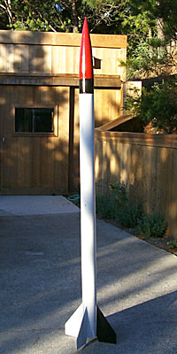
I've chosen a scale rocket, so I want the paint job to look good and be reasonably prototypical. As always with matters of scale rockets, we turn to Rockets of the World, available from ARA Press and various book stores. In the third edition, the Tomahawk info. starts on page 139. (RotW is a wonderful book and if you don't have it yet, I strongly urge you to buy it.) As we can see on page 140, the I.Q.S.Y. Tomahawk had a red nose cone with a black band below it, a white body and one black fin. There is also some bolt detail between the fins and on the black band and base of the nose cone.
When painting multiple colors, always start with the lightest color first. It's much easier for darker colors to cover lighter ones than vice versa. The Tomahawk is basically white with other colors in small places so I started by painting the booster and payload sections white. The nose cone was painted red separately and set aside.
With paint it's especially important to use light coats. The first coat should be little more than a light mist. The second coat should cover most of the details and the third and fourth coats should make the color nice and even. If you apply the paint too heavily, you will get sags and runs in the paint, which will require you to sand it off and start over.
Allow the base paint coat to dry fully. This can take up to a day, even in warm weather. Check your spray can for cure times. I like Krylon® spray paints, and many people like Rustoleum® paints. It's worth paying more for brand name paints because they are more forgiving on recoat times. Check the can to make sure the paint is "recoat any time" before you buy it.
 When the base coat is dry, you can mask off areas for other colors. Plan
your colors carefully so that you can do the minimum amount of masking.
Use good tape for this. Regular "masking tape" doesn't necessarily provide
a clean edge. I like the green 3M Fine Line tape for masking edges. This
tape also comes in different widths for making stripes or other effects.
When masking straight lines, use wide tape as it tends to stay straight.
When the base coat is dry, you can mask off areas for other colors. Plan
your colors carefully so that you can do the minimum amount of masking.
Use good tape for this. Regular "masking tape" doesn't necessarily provide
a clean edge. I like the green 3M Fine Line tape for masking edges. This
tape also comes in different widths for making stripes or other effects.
When masking straight lines, use wide tape as it tends to stay straight.
Once your edges are defined with good masking tape, cover the areas of the body which are not to be painted with paper. Newspaper works, although the green paper rolls are very convenient. Use ordinary masking tape along the edges of the paper to stick it to the good tape. Be sure to cover the rocket well as overspray from spray cans travels surprisingly far.
 Go ahead and paint your next color. This process can be repeated as many
times as necessary to get all the colors you need for your rocket.
Go ahead and paint your next color. This process can be repeated as many
times as necessary to get all the colors you need for your rocket.
If you stick with the same brand of paint, you should be able to just spray the colors on top of each other with no preparation. This often means compromising on the actual colors you want, but you can usually get ones that are close enough. If you really are intent on getting prototypical colors, consider hobby shop paints such as Testors®. While these are expensive and come in small cans, they have an excellent color selection.
Decals
Your kit may come with decals or it may not. My Tomahawk didn't come with any decals and would be fine just painted. However, I like the last little touch that comes with some fine details. I decided to make my own decals based on the detailed drawings in Rockets of the World using decal film and my Alps printer. See the Making Decals article in INFOcentral for the technique. There are also several sources for custom decals.
There are two kinds of decals: water transfer and pressure sensitive. The water transfer decals are a very thin film on top of a paper back. When soaked in water, the film slides off the back and onto the surface. Pressure sensitive decals (really stickers) also have a backing, but they are thicker and when you peel them off, they are sticky without water. See the Applying Decals article in INFOcentral for decal tips.
In the last lesson (lesson 5), we will install the recovery system, check stability
and pick motors to fly this baby!
Lesson 5: Preparing to Fly
In this lesson, we will install the recovery system, check stability and choose motors.
Weight and C.G.
Now that you have the rocket painted and assembled, you can get the final weight. Install the recovery system and assemble the rocket, including everything necessary for flight. Weigh the rocket at this point. This is your "dry weight." The weight is critical for determining the parachute size and for accurate simulations.
Then, determine the center of gravity (C.G.) of your rocket by balancing it. This is the dry C.G. Balance again using a weight which simulates the loaded weight of the heaviest motor you plan to fly. This is your liftoff C.G. You now have the numbers you need to verify the stability of your rocket.
Recovery System
Now that you have the final weight, you can determine the size parachute needed. Add the dry weight of the rocket to the burn-out weight of the largest motor you plan to fly. To determine the burn-out weight, subtract the propellant weight from the total weight of the motor. (For high-power motor information, see ThrustCurve.org.)
See the Main Chute Sizing article in INFOcentral for guidelines on parachute sizing. You can usually use the parachute which comes with your kit as long as you didn't add too much weight. West Coast fliers should be warned that many kits are designed for the smaller and softer fields in the East, which may result in a smaller than ideal 'chute.
If you decide to replace the 'chute with an after-market one, you can use the size guidelines of the manufacturer to determine which size 'chute to use. Obviously, larger 'chutes will bring your rocket down more softly, but will cause it to drift farther. If you have plenty of recovery area, round up to the next larger size. If you have a soft grassy field, you can round down.
Computer Simulation
If you rocket is of normal rocket proportions with reasonably large fins, as my Tomahawk is, there will be little question of stability. However, it's always a good idea to make sure. To do this, we need to calculate the center of pressure (C.P.) of our airframe. There are many programs which can do this. My personal favorite is RockSim by Apogee Components. (See the ThrustCurve.org simulators page for more options.)
Above you can see a screen shot from RockSim with the airframe entered into the program. You can see that I've already run simulations on the two motors I plan to fly, an I357 and a K550. The 38mm I357 is a nice level 1 motor for getting large rockets off the pad and the 54mm K550 is one of my all-time favorite motors. You can see the calculated C.P. is well behind the measured C.G (almost three calibers) even with the K550.
RockSim will calculate the weight of the rocket based on the materials you specify. However, it can only be as accurate as its parts database and the amount of detail you enter. I prefer to override the weight and C.G. it calculates with the actual ones once I have them. The menu item Rocket|Design... will bring up a tabbed dialog and the last page allows you to specify these values. Note that you should specify the dry weight and C.G. of the rocket and RockSim will calculate the flight values based on the selected motor.
If you fly electronics, you don't really need to figure out the delay times, but it's still nice to know more or less how high your rocket is going to fly. If you are flying with motor ejection, you definitely need to run simulations to figure out your delays.
RockSim will show you the optimal delay length when you test fly a motor. To choose the best delay, you should run a simulation with the ones just shorter and just longer than the optimum. Look at the Velocity at Deployment column to choose the delay which gives you the lowest speed at opening.
You are now ready to fly! I hope you have enjoyed this series and have many great flights on your rocket.