AGM-33 Pike
In an October 2013 discussion on the ROC email list, various Madcow Rocketry kits were discussed, so I took a look at their line-up.
There are a few kit manufacturers making filament-wound fiberglass rockets now (of which there were none after the demise of Dynacom a decade ago). I'd built two Dynacom kits long ago (the 4" Python and 5" Bull Pup) and I thought it would be fun to see the state of modern fiberglass kits.
After taking a look at their rockets, I chose the AGM-33 Pike since it looked cool, and the 5.5" airframe is a good size. (I almost chose the Sensor, but those swept-back fins looked too fragile.)
The Pictures
Painting was done in a rush for Aeronaut 2015, but it turned out that I was unable to attend anyway.
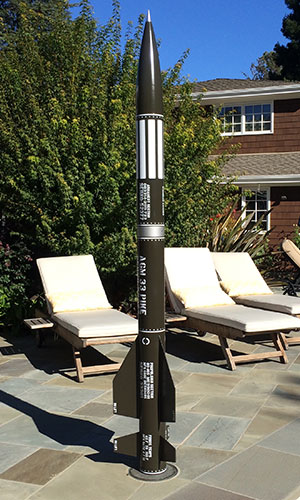
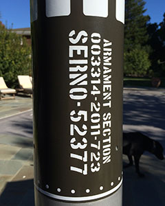
The color came out darker than I expected, but I got Mark Hayes to make me a version of his excellent vinyl decals in white; see Stickershock23.
There are quite a few flaws with my paint job, as I'm still learning how to get good results with automotive paints, but it looks good all together.
Aeronaut 2017
The maiden flight was at Aeronaut in August 2017. After Friday's perfect flight of my Sky Scraper the previous day, I was ready for a more ambitious flight on Saturday. In fact, I decided to fly this on an AeroTech M685, another long-burn motor and one I'd never flown before.
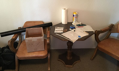
I build the motor Friday night in Bruno's per long-standing tradition. This is a 6-grain 75mm motor, so it looks quite impressive across the arms of the chair.
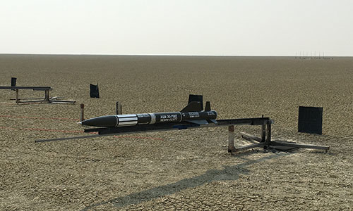
This model of a missile looks good horizontal, and I thought quite menacing on the rail before being raised.
I launched about 10:30am on Saturday August 5th, so there was little or no wind. The rocket landed about a half mile down range, laid out "pretty as a picture".
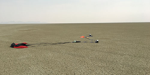
The flight appeared normal and recovery was perfect, although I was a bit surprised that the G-Wiz was beeping out only 11,146' (3397m) since simulation predicted 15,500' (4720m).
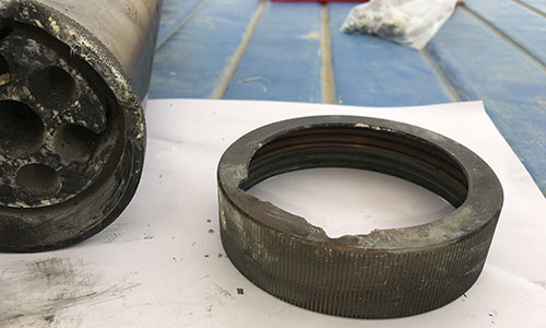
When I went to clean the motor case, it became apparent why I'd gotten much less altitude. Two of the outer throats of the medusa nozzle cracked and thrust was directed to the side, torching two sections of the aft closure and two areas of my AeroPack retainer.
Viewing the launch photos afterwards didn't show anything dramatic, although perhaps a little correction at about 100' (30m) above ground.
The Kit
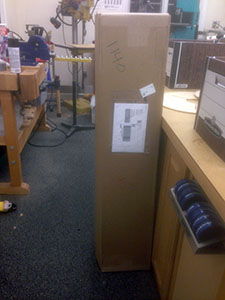
The kit arrived in less than a week, in a nice large cardboard box. I was excited to open it; this was the first high-power kit I'd built for many years.
 |
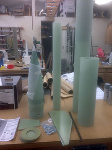 |
Above left you can see the kit in its box, a bit battered but in fine condition. Above right are the parts for the kit, all just as listed in the instructions. The only thing needed in addition are rail buttons and a motor retainer, plus the recovery system.
This kit is certainly beefy, with giant U-bolts and heavy threaded rod. But I guess "over designed" is the name of the game for these fiberglass kits. At any rate, I will build it as nearly stock as I can bring myself to do.
The kit comes already prepared for dual deployment, which is a great touch. My only complaint was that the kit instructions didn't include an exploded view diagram.
The Build
I decided to follow the instructions as closely as I could, making only minor improvements where I thought they were necessary. The instructions are nicely done, with lots of pictures and good auxiliary information, such as how to prepare surfaces for bonding.
Bulkheads and CRs
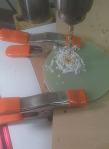
Following the instructions, I started with the bulkhead plates. I decided to drill holes for RouseTech CD3 CO2 systems in both pairs of plates before assembly.
I drilled the four holes through all four bulkheads as indicated in the instructions. Then I drilled two 1/8" holes through all four as well; one for the e-match wire and one as a pilot for the larger CD3 holes.
 |
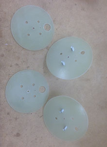 |
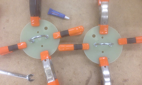
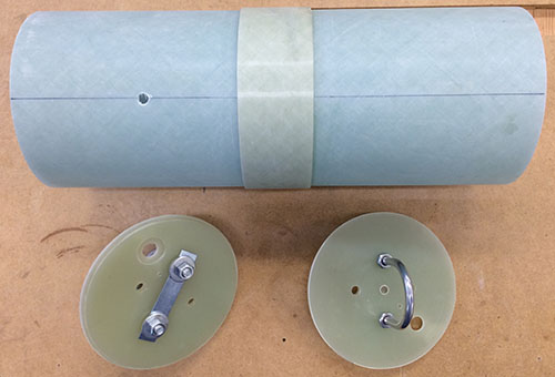
In the picture, above right, you can see the ½" hole for the CO2 cartridge neck on the larger bulkhead and the matching 1" hole through smaller bulkhead for clearance. Otherwise, the two pairs of bulkheads (one for each end of the electronics bay) were drilled and bonded together following the instructions.
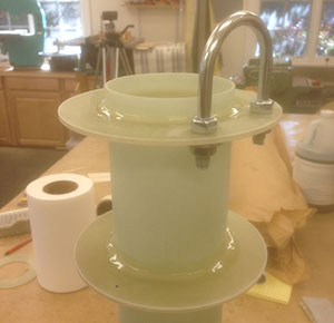
The other modification to the kit was in the nose cone bulkhead. I just couldn't let all that space in the nose go to waste, so I cut a new bulkhead with a 54mm hole to mount a small bay for my TelemetryPro "Kate" GPS tracker.
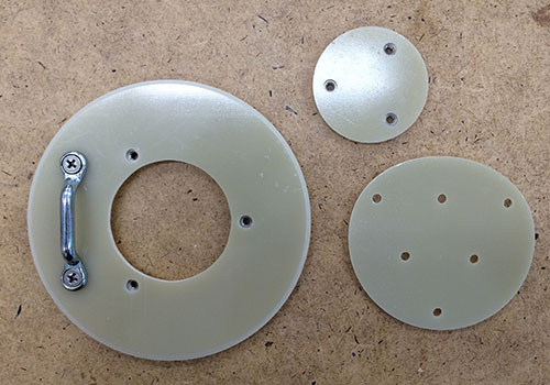
The 54mm tube that houses Kate screws to the cover and the cover screws until the bulkhead. Below you can see the bulkhead at the forward end of the nose coupler with the bay installed.
As in the original part, the bulkhead fits at the forward end of the nose coupler, adding a bit more main recovery space.
Finally, the forward centering ring was drilled for the U-bolt and two CRs were bonded to the forward end of the motor mount tube.
Electronics Bay
The rocket has generous (huge!) space for electronics with a 14" long electronics bay built into the coupler that joins the forward and aft airframe sections.
I really appreciate the newer kits designed with dual-deployment built in. Although this particular model is more of a beast than an altitude bird, it's always a good option to have.
The huge amount of space for the electronics bay is dominated by two 5/16" threaded rods that run through the center. This means no GPS tracker (or other radio transmitters) in this part of the rocket!
 |
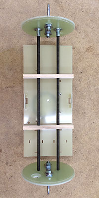 |
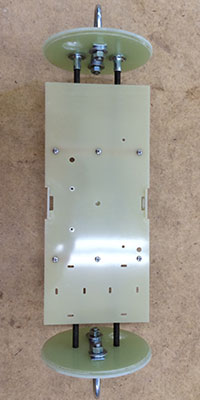
In the photos above, you can see how generous a space this is; my electronics plate doesn't even use all the space. (I cut it out of a 12" square pieces of fiberglass sheet.)
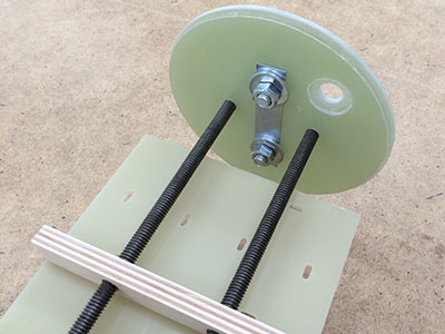
And here is the end from the inside, showing how it all holds together. That's a lot of steel!
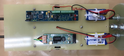
And finally the electronics bay loaded with dual altimeters. This rocket is supporting old-school units: an AED R-DAS and a G-Wiz HCX. These units are both designed to work with 9v batteries, but I decided to drive them with 3-cell LiPos, which is more convenient and provides much more power.
Aft Body and Fins
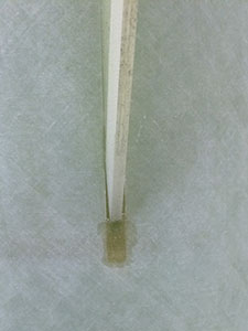
Test-fitting the fins into the slots, I discovered that the slots were much longer than necessary, and one of them were much too narrow. At least they were evenly spaced around the circumference.
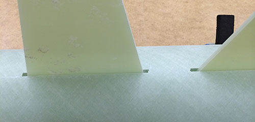
four of the six fin slots needed only minor filing and sanding for a perfect fit, but I had to get out the Dremel and grind the other two to the correct width (adding something near 1/16").
 |
 |
Following the instructions, I tacked the three forward (large) fins in place with CyA. In addition, I used a guide to make sure the fins came out at the right angle (120° apart). Once I had the fins tacked into place, I put tape over the holes made by the excessively long fin slots and applied the inner fillets. This rocket has a lot of long fillets to do!
Once the forward fins were secured internally, I mounted the aft fins. Since the slots are way too long, I made a quick guide to align the aft fins with the forward ones and space them evenly apart. (The forward fins butt against the middle centering ring, and the aft fins are spaced relative to the forward ones.)
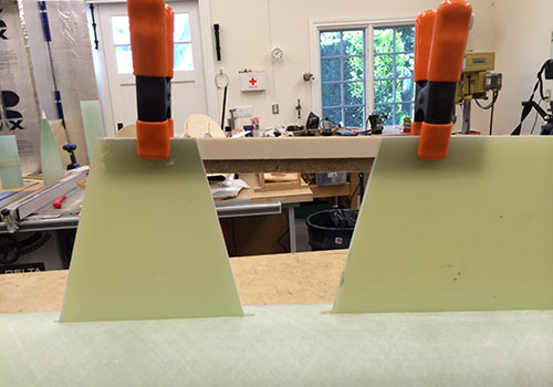
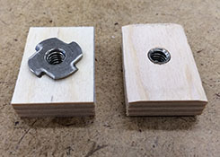
For this heavy a rocket, I wanted to make sure the rail buttons were securely mounted. These are large rail buttons, mounted with a ¼-20 screw, so I mounted the T-nut into pieces of 12mm birch ply to create a large area for bonding.
 |
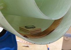 |
If you look closely at the right plate (left photo above), you can see how I mitered the edges of the plywood to create a large surface area on the inside of the tube.
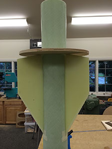
Finally, I decided to fill the entire fincan with 2-part expanding foam, to lock everything together. I made a short video to show this process. After that, the aft centering ring was fully bonded with epoxy, completing the aft section.
Finishing
One nice thing about fiberglass, is it's easy to finish; the surface is pretty much ready for primer as-is.
I had been meaning to get back to using automotive paints and try to improve my techniques, so I took this rocket as an opportunity to do so and make a how-to video at the same time.
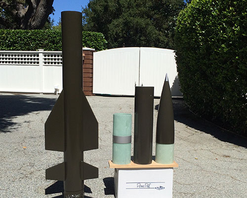
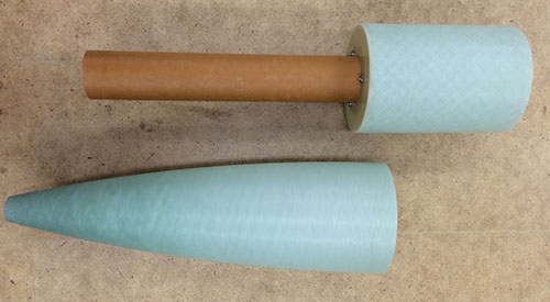
Above you can see the parts after being painted. The color I chose, "olive drab" (brand code 42955), turned out to be a lot more drab than olive. As a result, I decided to use white lettering instead of the black I had planned on. At least the bare aluminum tip and switch band silver give it some contrast.